
Wheel Bearing Assembly

a technology of bearing assembly and wheel bearing, which is applied in the direction of mechanical equipment, rotary machine parts, transportation and packaging, etc., can solve the problems of mass/weight and cost penalties, noisy or vibrating bearing assembly, and easy to receive brinell marks on the wheel rotating bearing assembly of the vehicl

Active Publication Date: 2015-01-08
SKF USA INC
View PDF3 Cites 9 Cited by
  • Summary
  • Abstract
  • Description
  • Claims
  • Application Information

AI Technical Summary

Benefits of technology

This patent is about a new design for bearing assemblies used in vehicles. The design helps prevent damage to the ball components during a side impact, which can cause deep stress concentrations. The design includes a small clearance between the wheel mounting component and the non-rotating component, which limits the axial travel of the component during a side impact. This prevents the ball components from shifting up the raceways and keeps them within a specific range of heights. The design is particularly useful for side-impact events and helps prevent damage to the bearing assembly.

Problems solved by technology

As combinations of larger diameter wheels, lower profile tires and more rigid or sensitive corner suspension components are being employed in newer vehicle platforms, the vehicle wheel rotating bearing assembly is much more susceptible to receiving “Brinell marks” or “brinelling” due to low-speed side impacts with objects such as curbs, such as a 3-mph curb-impact, and radial impacts with objects such as potholes, with high-strength wheels and low-profile tires.
The typical result of a radial or side-impact Brinell event is the development of a noisy or vibrating bearing assembly in the vehicle.
A common design solution is to increase the diametral or axial size of the bearing and / or the size or number of rolling elements of the bearing, which usually results in mass / weight and cost penalties and renders the bearing design inefficient in terms of straight running and cornering capabilities.
This approach, however, raises processing costs.
The penalty with all of the traditional ideas is the addition of mass / weight, rotational torque, and costs of the bearing and mating corner components to the bearing.

Method used


Image

  • Wheel Bearing Assembly
  • Wheel Bearing Assembly
  • Wheel Bearing Assembly

Examples


Embodiment Construction

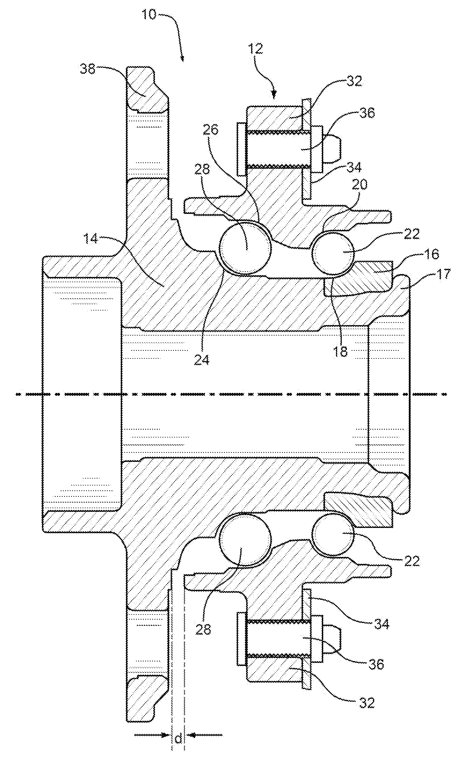
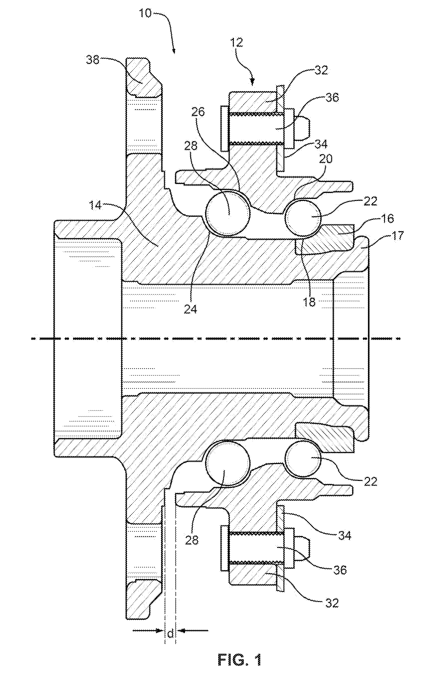
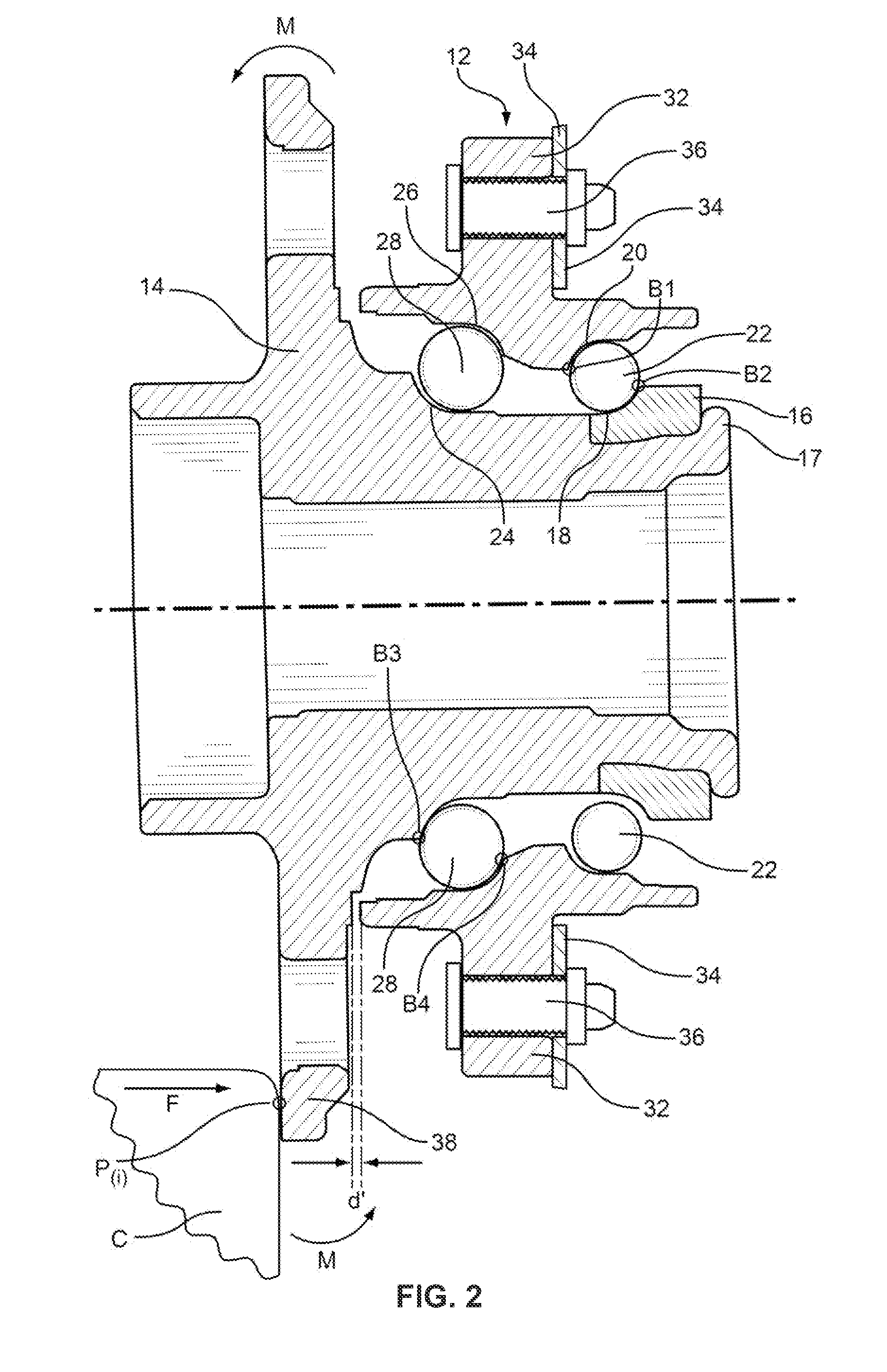
[0035]Referring to FIGS. 1 and 2, the problem of impact Brinell damage in existing wheel bearing assemblies is illustrated. Note that FIGS. 1 and 2 are not intended to accurately represent any particular prior art or existing assembly, but rather only to illustrate the problem. In FIG. 1, a representative existing wheel bearing assembly 10 is shown, having a non-rotating outer ring component 12, a rotating inner ring component 14, and an inboard inner bearing ring 16 damped in place by an integrally formed rotating tab 17. Inboard inner bearing ring 16 defines an inboard inner bearing raceway 18, and non-rotating component 12 defines an inboard outer bearing raceway 20, which together encapsulate an inboard ballrow of ball components 22. Likewise, rotating component 14 defines an outboard inner bearing raceway 24 and non-rotating component 12 defines an outboard outer bearing raceway 26, to accommodate an outboard ballrow of ball components 28. Non-rotating component 12 includes an ...


PUM


Abstract

A passenger automotive vehicle wheel bearing assembly having improved impact Brinell resistance is provided. Due to a controlled gap between a rotating component and a non-rotating component or a vehicle suspension structure, the non-rotating component or the vehicle suspension structure is permitted to share impact loads caused by a sufficient radial or side impact (such as a pothole or curb impact) to the rotating component, thus preventing excessive loads from being transmitted to rolling elements, and providing greater resistance against Brinell impact damage that would generate a noise and / or vibration condition in the bearing assembly. Wheel bearing assemblies according to the invention provide increased impact Brined resistance while avoiding excessive contact between the rotating component and the non-rotating component or the vehicle suspension structure during extreme cornering maneuvers.

Description

CROSS-REFERENCE TO RELATED APPLICATION[0001]This application is a continuation-in-part of U.S. patent application Ser. No. 12 / 291,144, filed Nov. 6, 2008, the entire specification of which is incorporated by reference.FIELD OF THE INVENTION[0002]The present invention relates to wheel bearing assemblies. More particularly, it relates to a wheel bearing assembly having improved side-impact and radial-impact Brinell resistance.BACKGROUND OF THE INVENTION[0003]As combinations of larger diameter wheels, lower profile tires and more rigid or sensitive corner suspension components are being employed in newer vehicle platforms, the vehicle wheel rotating bearing assembly is much more susceptible to receiving “Brinell marks” or “brinelling” due to low-speed side impacts with objects such as curbs, such as a 3-mph curb-impact, and radial impacts with objects such as potholes, with high-strength wheels and low-profile tires. Brinell marks are microscopic indents in the bearing raceway that occ...

Claims


Application Information

Patent Timeline
IPC IPC(8): B60B27/00F16C33/58F16C19/50
CPCB60B27/0005F16C19/505B60B2380/12B60B2380/774F16C33/586B60B27/001B60B27/0084F16C19/184F16C19/386F16C19/497F16C19/522F16C21/00F16C39/02F16C2240/30F16C2326/02
Inventor MEEKER, STEVEN E.JOHNSON, DAVID N.HINDS, KELLY S.BUYNACEK, CONNIE J.GROVER, MARTIN P.
Owner SKF USA INC
Learn More