
Method and device for estimating light scattering

Inactive Publication Date: 2015-01-01
THOMSON LICENSING SA
View PDF5 Cites 3 Cited by
  • Summary
  • Abstract
  • Description
  • Claims
  • Application Information

AI Technical Summary

Benefits of technology

The invention aims to reduce the time required to compute a realistic live display of light passing through media.

Problems solved by technology

The calculations required to simulate the scattering of light in such heterogeneous media are then very costly and it is thus not possible to calculate analytically and interactively the quantity of light scattered by a heterogeneous participating medium.
Though these methods are perfectly adapted for a studio use in post-production for example and provide a good quality display, these methods are not adapted in the context of live interactive conception and composition of a heterogeneous participating media.
This solution cannot however be considered as a live display solution as some pre-processing must be applied offline to the participating media to be able to calculate projection coefficients representing the media that will be used for image synthesis live calculations.

Method used


Image

  • Method and device for estimating light scattering
  • Method and device for estimating light scattering
  • Method and device for estimating light scattering

Examples


first embodiment

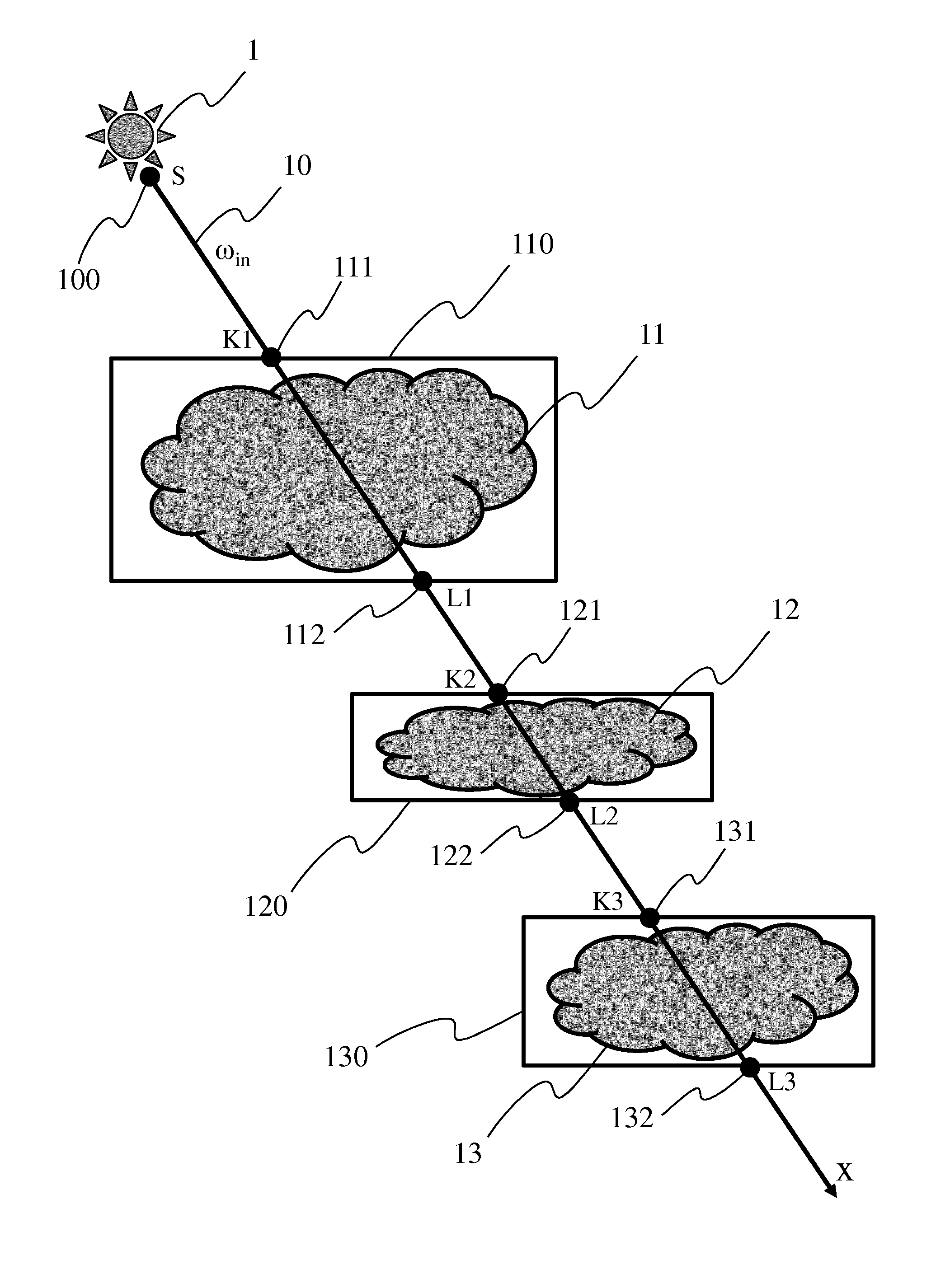
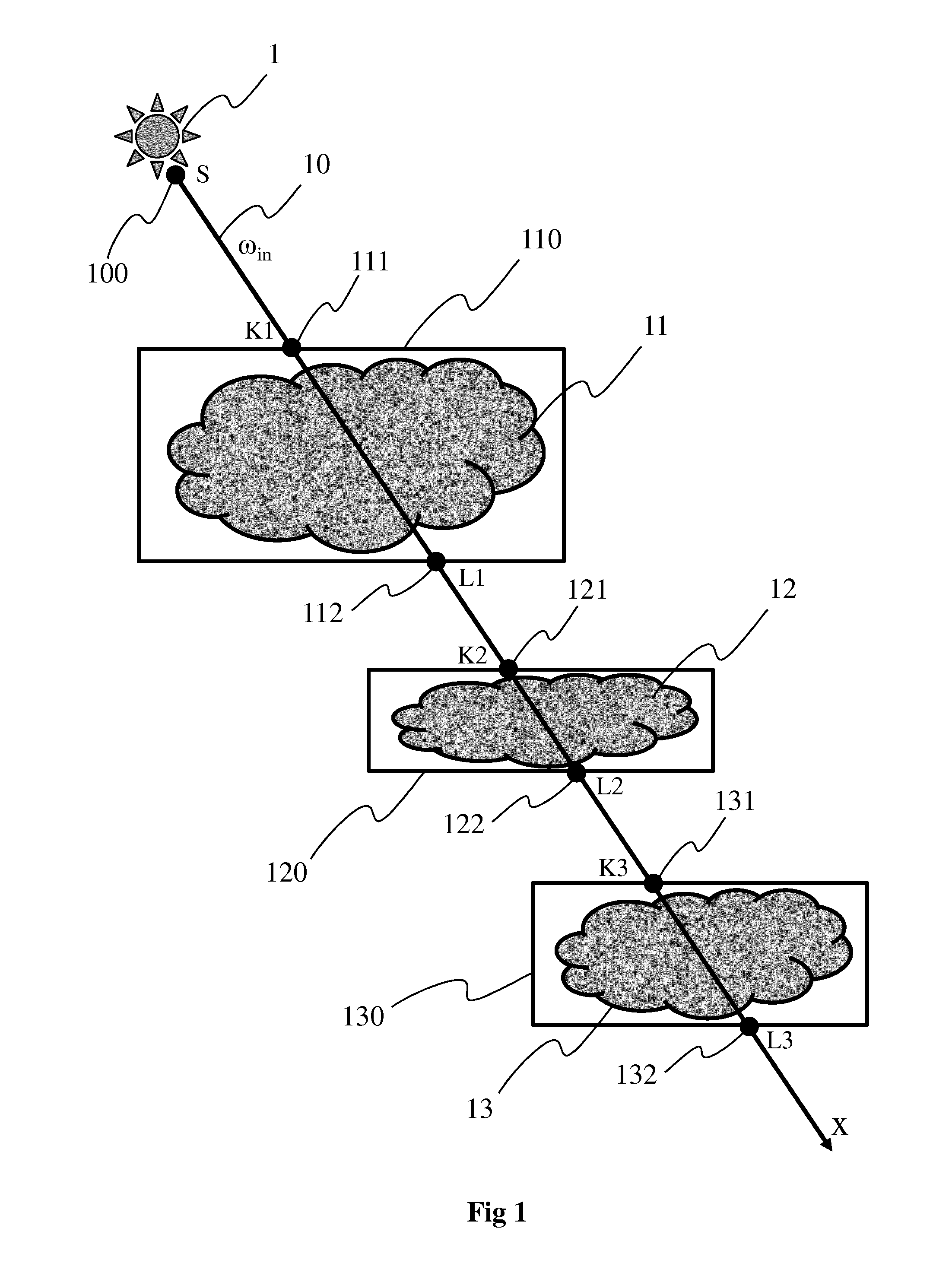
[0045]FIG. 4A illustrates a first embodiment for determining a pseudo-metric function d(x) 42 representative of the distance along the light ray 10. The function d(x) 42 is represented with a segmented line on FIG. 4A. The pseudo-metric function d(x) 42 is such that the distance along the light ray increases when inside a participating medium 11, 12 and 13 and is stationary outside any participating media. Unlike a metric function (representative of an Euclidian distance) which is strictly increasing, a pseudo-metric function has the advantage of being monotonic with one or more stationary parts. The pseudo-metric function is advantageously determined according to the intersection points K1 111, L1 112, K2 121, L2 122, K3 131 and L3 132 between the light ray 10 and the participating media 11, 12, 13, with regard to x. For an element M1 (a point, a particle or a ray sample if the light ray 10 is discretized into a number Y of samples) belonging to the light ray 10 and to the first pa...

second embodiment

[0047]FIG. 4B illustrates a second embodiment for determining the pseudo-metric function d(x). As to simplify and speeding up the computations needed for determining d(x), the square function v(x) defined with regard to FIG. 4A is first expressed with second projection coefficients representing the function v(x) 410 in a functions base, for example a DCT basis. The function v(x) once projected in the functions base (composed of N basis functions bi) is defined with:

v(x)=Σi=0Ndibi(x)  equation 5

[0048]wherein di is the ith coefficient of the basis function bi defined with:

di=∫(x)bi(x)dx  equation 6

[0049]where v(x)=1 or any value different from 0 if x is within a participating medium and 0 otherwise. To obtain the pseudo-metric function d(x), v(x) is integrated, which gives:

d(x)=∫0xΣdibi(x)dx  equation 7

d(x)=Σdi∫0xbi(x)dx  equation 8

d(x)=Σdi(Bi(x)−Bi(0))  equation 9

[0050]where Bi is the primitive of bi and Bi(0) is the primitive of bi at the level of the light source, i.e. at point S 1...


PUM


Abstract

A method and device for estimating the quantity of light received by an element of at least a participating medium belonging to a light ray crossing the at least a participating medium and having as origin a light source. As to optimize the estimation and the rendering of the at least a medium, the method comprises determining a pseudo-metric function according to intersection points between the participating medium and the light ray, the pseudo-metric function representing the distance only along the part(s) of the light ray crossing the participating medium; estimating first projection coefficients in a functions basis, the first coefficients being representative of an extinction function along the light ray according to the pseudo-metric function; and estimating the quantity of light received by the element according to the first projection coefficients.

Description

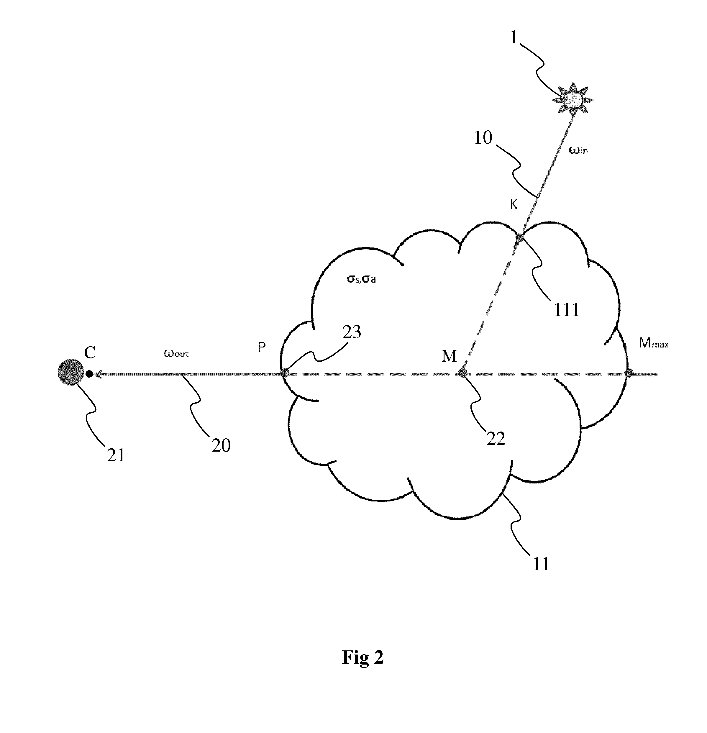
1. DOMAIN OF THE INVENTION[0001]The invention relates to the domain of image synthesis and more specifically to the domain of lighting simulation in a virtual environment comprising one or more participating media. The invention is also understood in the context of special effects for a live composition.2. PRIOR ART[0002]According to the prior art, different methods exist for estimating the quantity of light received and scattered in participating media such as for example fog, smoke, dust or clouds. Participating media correspond to media composed of particles in suspension that interact with the light modifying particularly the trajectory and intensity.[0003]Participating media can be broken down into two groups, namely homogenous media such as water and heterogeneous media, such as smoke or clouds. In the case of homogenous participating media, it is possible to calculate analytically the attenuation of the light transmitted by a light source. In fact, due to their homogenous nat...

Claims


Application Information

Patent Timeline
IPC IPC(8): G01J3/44G01J1/42
CPCG01J1/42G01J3/4412G06T15/06G06T15/506
Inventor GAUTRON, PASCALMARVIE, JEAN-EUDESDELALANDRE, CYRIL
Owner THOMSON LICENSING SA
Learn More