
Steam cracking process and system with integral vapor-liquid separation

a technology of steam cracking and vapor-liquid separation, which is applied in the direction of liquid-gas reaction process, chemical/physical process, chemistry apparatus and process, etc., can solve the problem of running cracking reaction at conditions lower than atmospheric pressure, and achieve the effect of improving the efficiency of cracking reaction

Active Publication Date: 2015-01-01
SAUDI ARABIAN OIL CO
View PDF2 Cites 9 Cited by
  • Summary
  • Abstract
  • Description
  • Claims
  • Application Information

AI Technical Summary

Benefits of technology

The present invention provides a process of making an improved sample holder for use in various applications, such as making semiconductor devices. The sample holder is designed to hold a semiconductor device in a stable position, during processing and other operations. By using the sample holder, the process of making semiconductor devices can be more efficient and accurate. The technical effects of this invention are improved efficiency and accuracy in the fabrication of semiconductor devices.

Problems solved by technology

The reaction normally occurs at atmospheric pressure; and running the cracking reaction at conditions lower then atmospheric pressures can be very uneconomical.

Method used


Image

  • Steam cracking process and system with integral vapor-liquid separation
  • Steam cracking process and system with integral vapor-liquid separation
  • Steam cracking process and system with integral vapor-liquid separation

Examples


Embodiment Construction

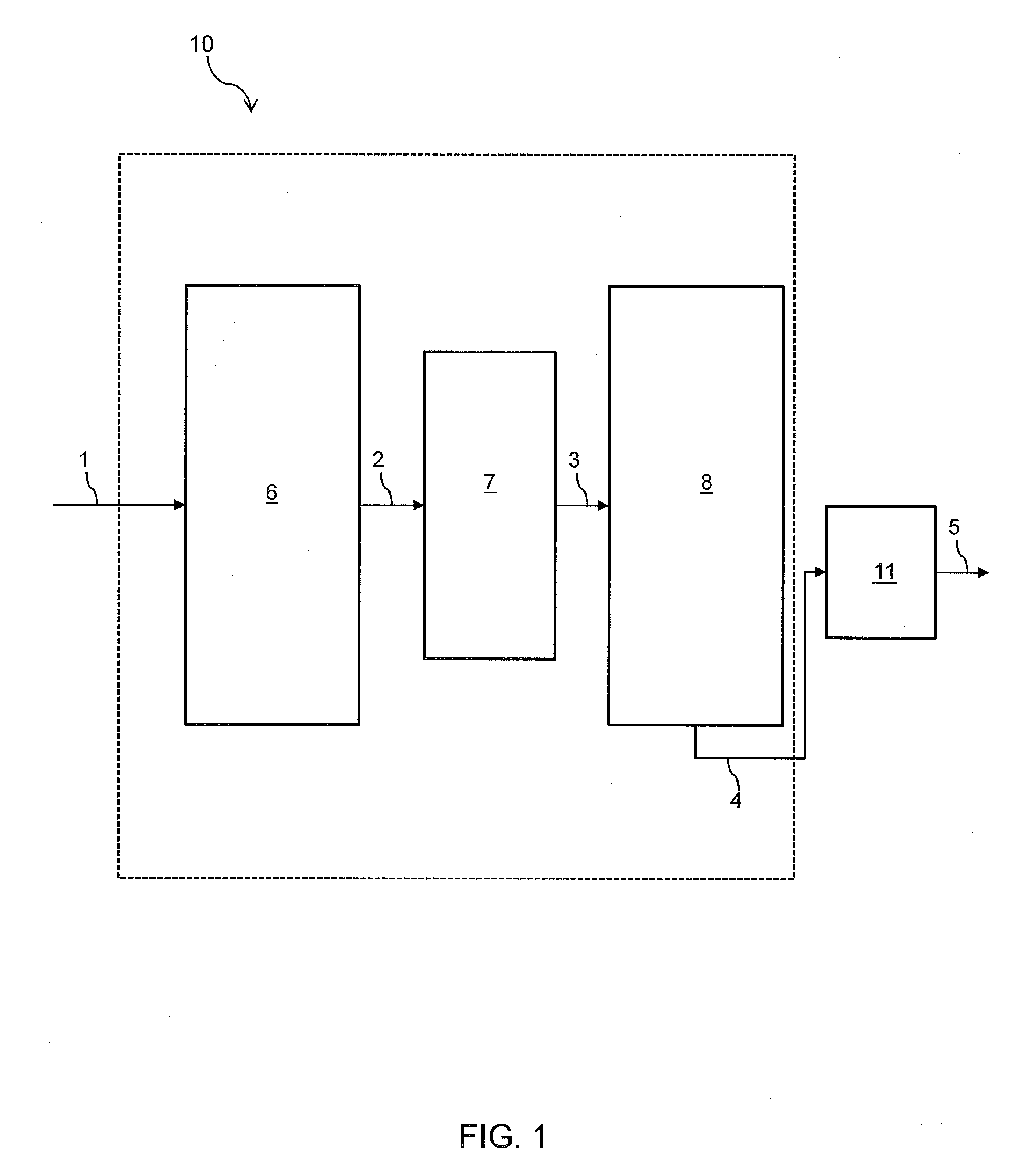
[0016]A process flow diagram for one embodiment of a steam cracking process with an integrated vapor-liquid separation is shown in FIG. 1. The integrated system generally includes a convection section and a steam pyrolysis section, with a vapor-liquid separation zone between the convection and pyrolysis sections.

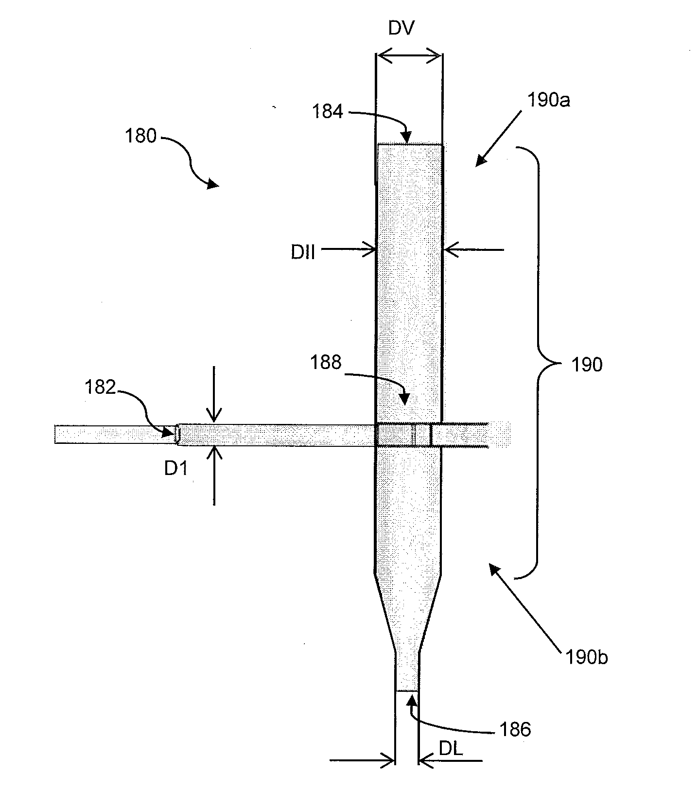
[0017]Steam pyrolysis zone 10 generally comprises a convection section 6 and a pyrolysis section 8 that can operate based on steam pyrolysis unit operations known in the art, i.e., charging the thermal cracking feed to the convection section in the presence of steam. In addition, as shown in FIG. 1 a vapor-liquid separation section 7 is included between sections 6 and 8. Vapor-liquid separation section 7, through which the heated steam cracking feed from convection section 6 passes, can be a separation device based on physical or mechanical properties of vapors and liquids.

[0018]In certain embodiments, vapor-liquid separation devices are illustrated by, and with reference to...


PUM


Abstract

An integrated vapor-liquid separation device is provided in conjunction with a steam pyrolysis cracking unit operation. In certain aspects, a feed is charged to the inlet of a convection portion of a steam pyrolysis unit where the feed is heated to conditions effective for steam cracking The convection section effluent is separated in a vapor-liquid separator and the separator vapor effluent is charged to the inlet steam cracking portion of the steam pyrolysis zone. The liquid effluent can be further processed, recycled within the system or a combination thereof. In additional aspects, a feed separated upstream of the convection portion of a steam pyrolysis unit using a flash vessel equipped with a vapor-liquid separator device described herein.

Description

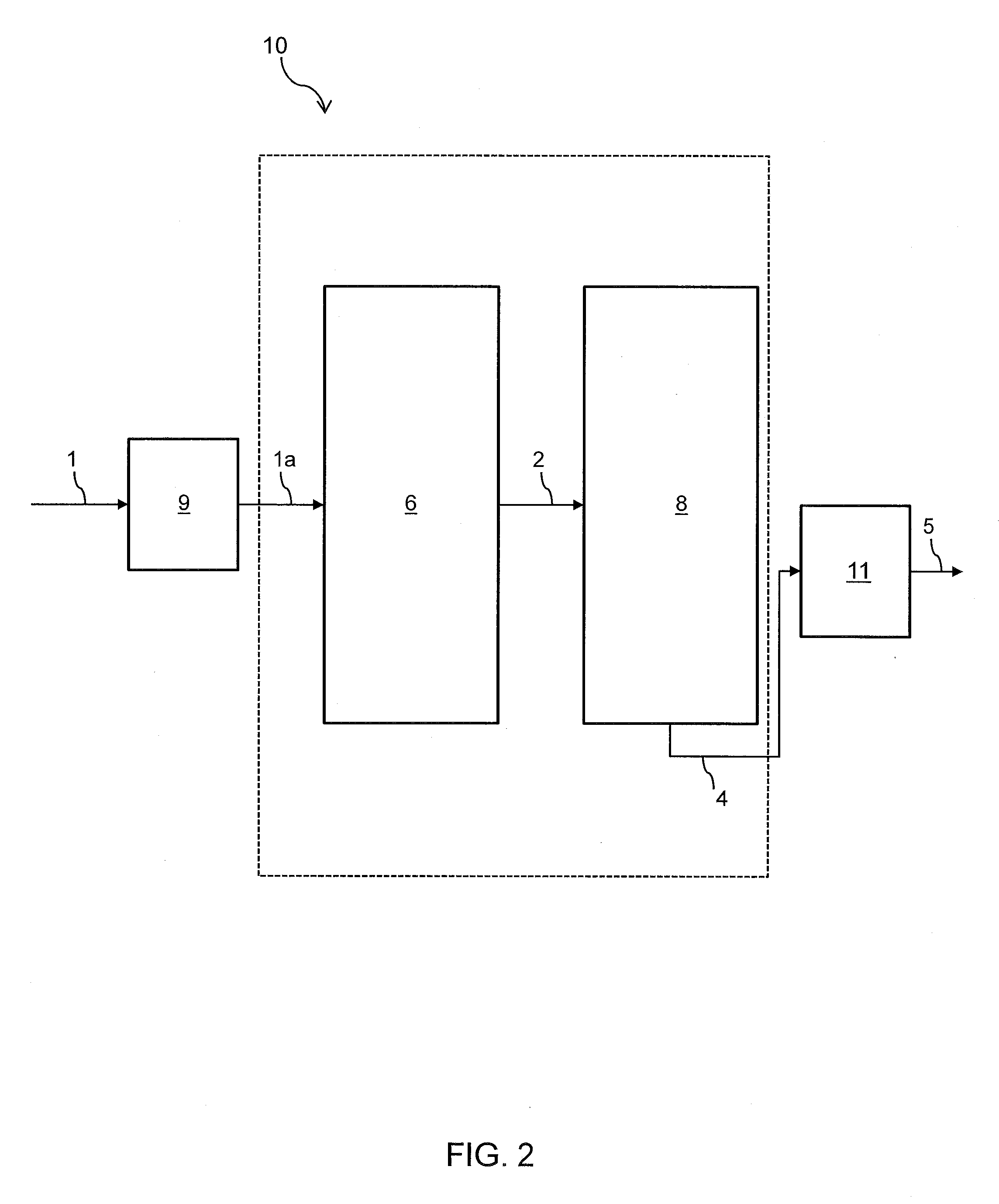
RELATED APPLICATIONS[0001]This application is a continuation-in-part of P.C.T. Patent Application No. U.S. 2013 / 033189 filed Mar. 20, 2013, which claims the benefit of priority of U.S. Provisional Patent Application Nos. 61 / 613,332 filed Mar. 20, 2012 and 61 / 792,822 filed Mar. 15, 2013, which are all incorporated by reference herein.BACKGROUND OF THE INVENTION[0002]1. Field of the Invention[0003]The present invention relates to an improved steam cracking process and system.[0004]2. Description of Related Art[0005]Steam cracking processes typically involve two main sections, the convection and pyrolysis section. The convection section of the steam pyrolysis cracking zone is used to heat the feed to the required reaction temperatures, often called the cross-over temperature, prior to entering the steam pyrolysis cracking unit, wherein the pyrolysis cracking reaction occurs. Steam pyrolysis cracking reactions typically convert a relatively heavy hydrocarbon feedstock, which may include...

Claims


Application Information

Patent Timeline
IPC IPC(8): C10G9/36
CPCC10G9/36C10G9/16
Inventor AKHRAS, ABDUL RAHMAN ZAFERBOURANE, ABDENNOURSHAFI, RAHEELABBA, IBRAHIM A.
Owner SAUDI ARABIAN OIL CO
Learn More