
Device for driving rear wheel of electric vehicle

Active Publication Date: 2014-12-25
HYUNDAI WIA
View PDF33 Cites 19 Cited by
  • Summary
  • Abstract
  • Description
  • Claims
  • Application Information

AI Technical Summary

Benefits of technology

The present invention provides a device for driving a rear wheel of an electric vehicle that can simplify the structure of a trailing arm by providing a fastening part with a large outer diameter at the wheel side. This allows for a more efficient and streamlined assembly of the motor from the exterior to the interior of the vehicle. Additionally, the invention can reduce the load on the motor cover, improve packaging performance, and protect the output shaft from bending. Overall, this device provides a more effective and efficient solution for driving the rear wheel of an electric vehicle.

Problems solved by technology

However, in the conventional rear wheel driving device of an electric vehicle, since the motor is assembled from a rear surface of the vehicle, it is quite difficult to install the components of the motor on the rear surface.
As an alternative option, the components of the motor are limitedly installed on side surfaces of the motor.
In addition, in the conventional rear wheel driving device of an electric vehicle, a motor fastening part is positioned inside a wheel, and a speed reducer fastening part is positioned outside the wheel, making a trailing arm have a complex structure.

Method used


Image

  • Device for driving rear wheel of electric vehicle
  • Device for driving rear wheel of electric vehicle
  • Device for driving rear wheel of electric vehicle

Examples


Embodiment Construction

[0037]The present invention now will be described more fully hereinafter with reference to the accompanying drawings, in which embodiments of the invention are shown. This invention may, however, be embodied in many different forms and should not be construed as limited to the embodiments set forth herein. Rather, these embodiments are provided so that this disclosure will be thorough and complete, and will fully convey the scope of the invention to those skilled in the art.

[0038]The terminology used herein is for the purpose of describing particular embodiments only and is not intended to be limiting of the invention. As used herein, the singular forms “a”, “an” and “the” are intended to include the plural forms as well, unless the context clearly indicates otherwise. It will be further understood that the terms “comprises” and / or “comprising,” when used in this specification, specify the presence of stated features, integers, steps, operations, elements, and / or components, but do ...


PUM


Abstract

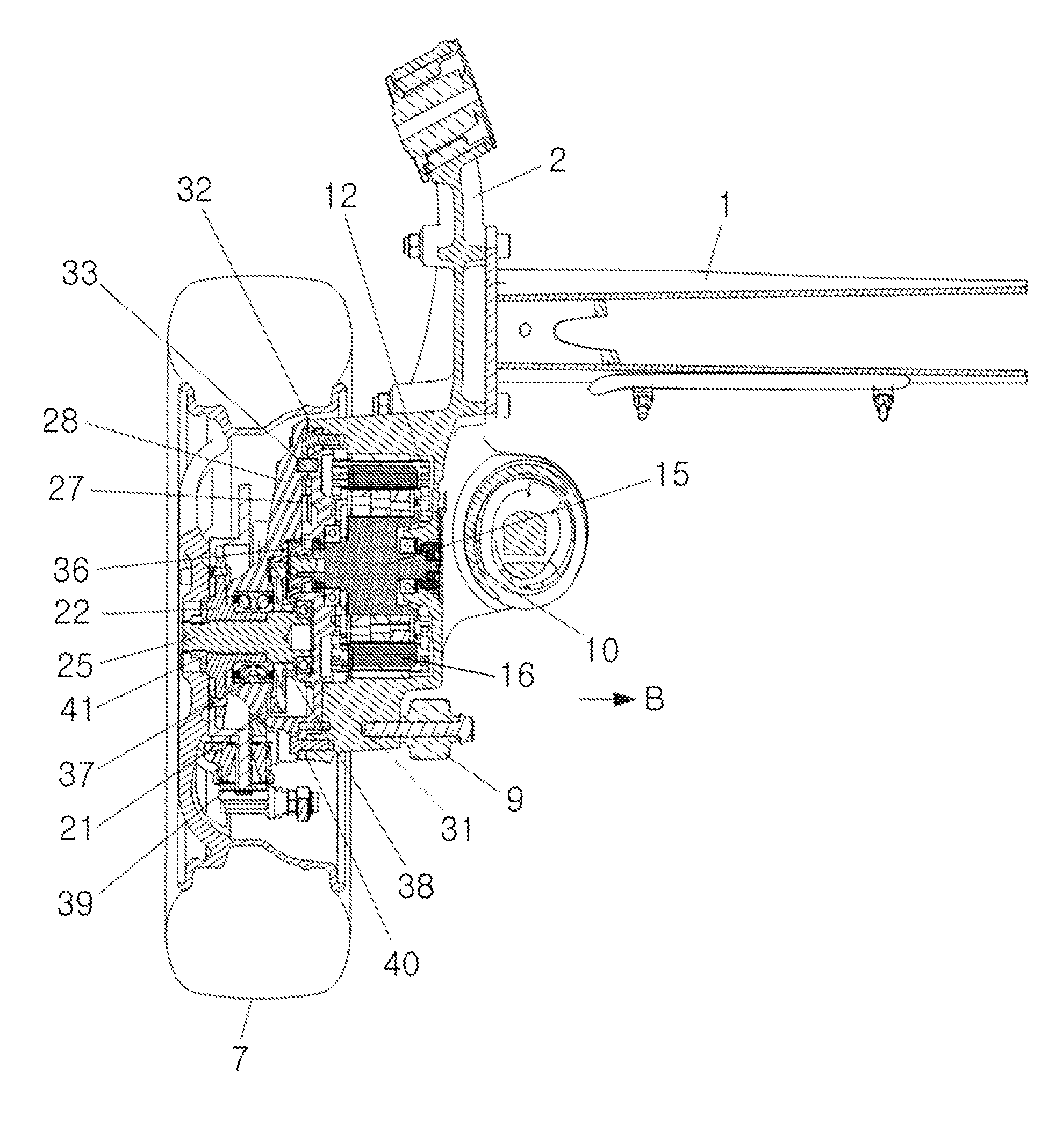
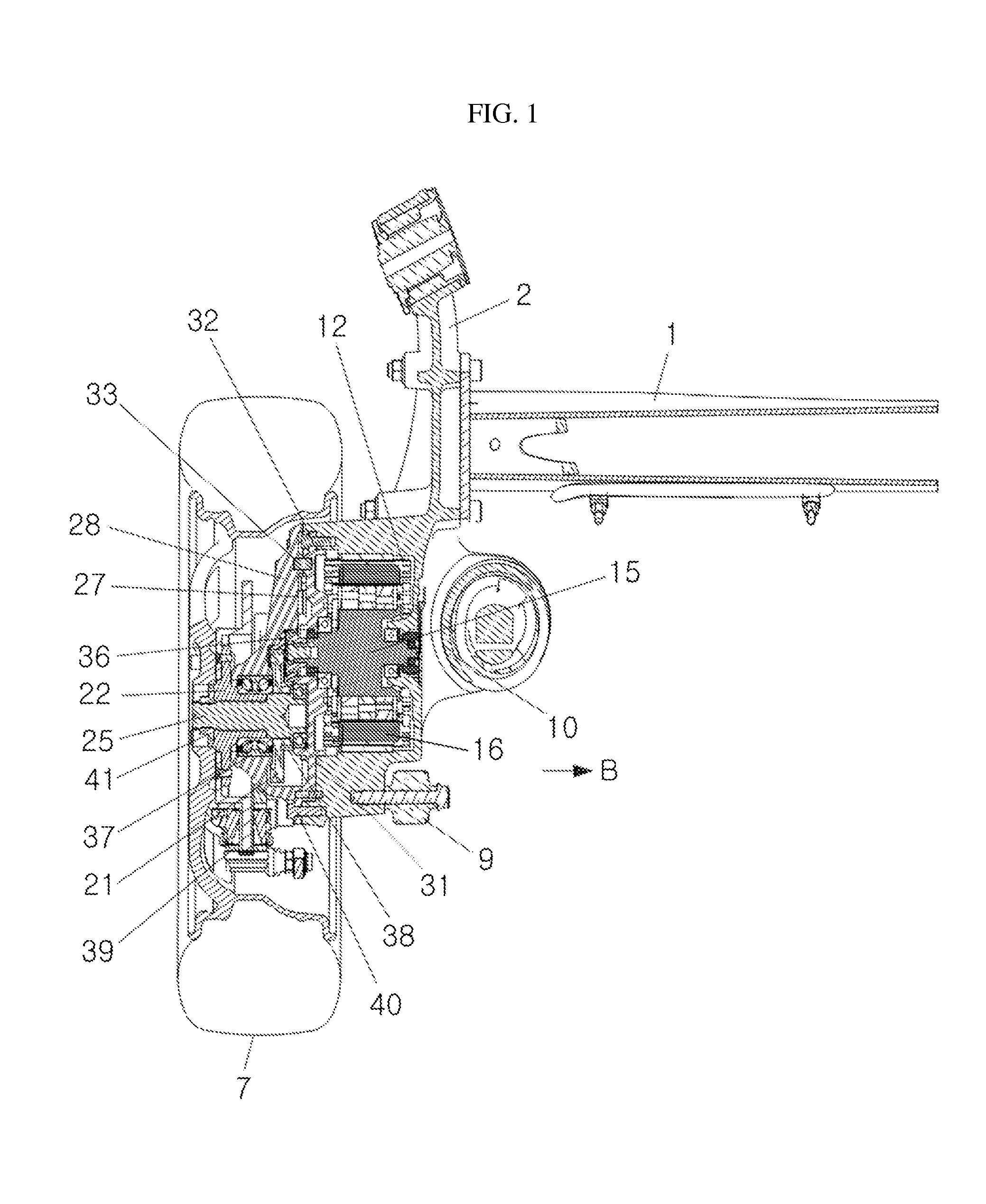
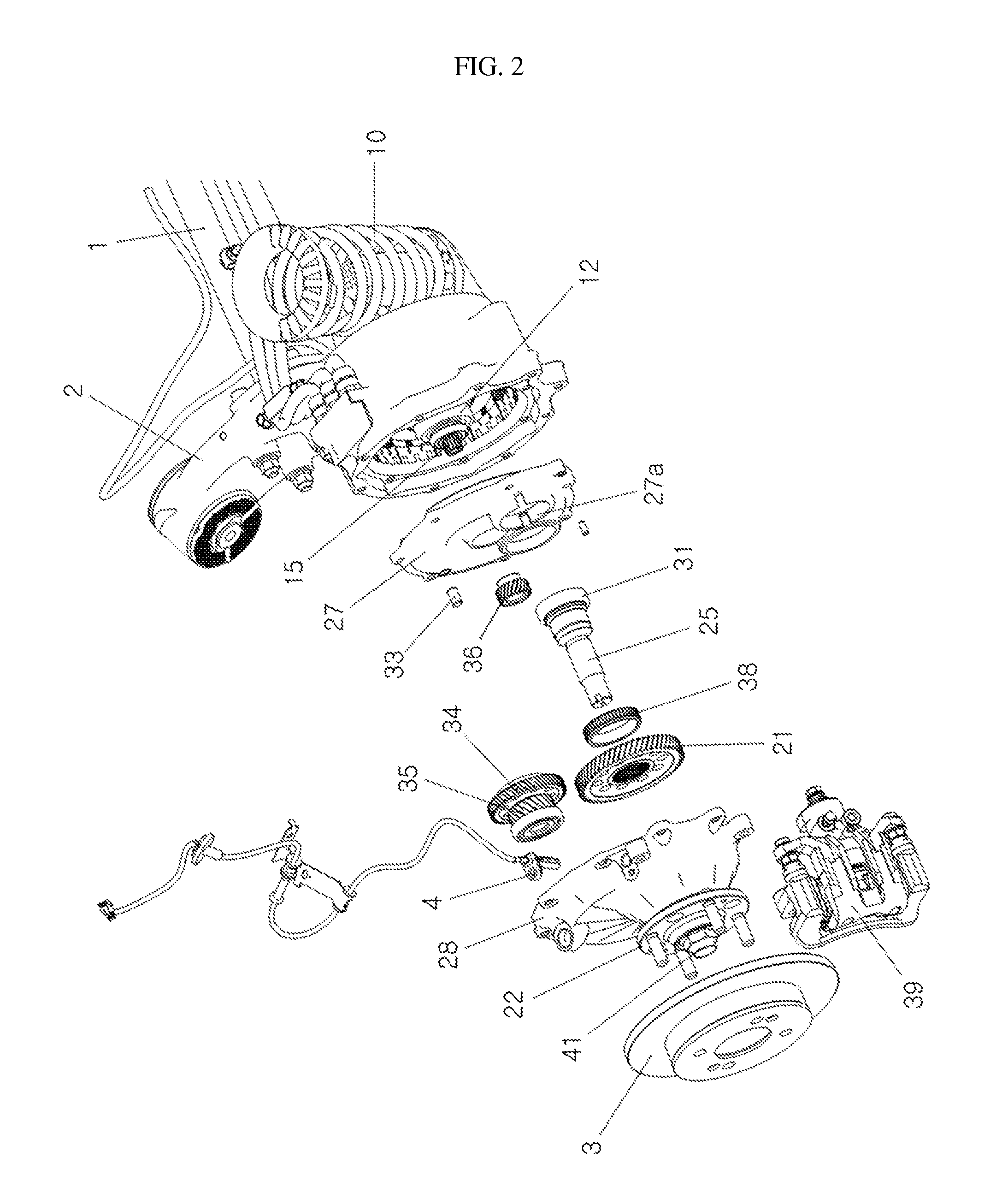
A device for driving a rear wheel of an electric vehicle is provided. In one embodiment, the rear wheel driving device includes a motor for supplying rotational power, a gear group connected to a rotor of the motor, a final gear connected to the gear group, an output shaft connected to the final gear and rotating, a hub installed on an outer circumferential surface of the output shaft using a nut, a wheel connected to the hub, an axle housing connected to the hub using a hub bearing, a motor cover protecting the motor and mounting an output shaft bearing, and a trailing arm connected to the axle housing using an axle housing bolt and configured to mount the motor from an exterior side to an interior side of a vehicle.

Description

CROSS-REFERENCE TO RELATED APPLICATION[0001]This application claims priority to and the benefit of Korean Patent Application No. 10-2013-0073299 filed on Jun. 25, 2013, which is herein incorporated by reference in its entirety.BACKGROUND OF THE INVENTION[0002]1. Field of the Invention[0003]Aspects of the present invention relate to a device for driving a rear wheel of an electric vehicle, which can assemble a motor from the exterior side to the interior side of a vehicle, can simplify a structure of a trailing arm by providing a fastening part having a large outer diameter at a wheel side, can reduce the load of a motor cover by fastening the motor cover to the inside of the trailing arm and fastening an axle housing to the outside of the trailing arm, and can improve packaging performance by assembling a final gear and a tone wheel on a rear surface of a wheel while nut-fastening an output shaft on a front surface of the wheel, which is a dead space.[0004]2. Description of the Rela...

Claims


Application Information

Patent Timeline
IPC IPC(8): B60K1/00B60K17/04B60G21/05B60K7/00B60L50/10
CPCB60K1/00B60K7/0007B60K2007/0061B60G21/051B60K2007/0038B60K17/043B60Y2400/3032B60G7/02B60K7/00
Inventor LEE, SANG MIN
Owner HYUNDAI WIA
Learn More