Mitral valve spacer and system and method for implanting the same

Active Publication Date: 2014-12-18
CARDIOSOLUTIONS
View PDF9 Cites 61 Cited by
  • Summary
  • Abstract
  • Description
  • Claims
  • Application Information

AI Technical Summary

Benefits of technology

The patent describes a heart valve implant that can be delivered through a flexible shaft. The implant has a flexible inflatable part that can bend to fit through delivery systems. It also has a part that is rigid enough to keep it in position. The implant can help reduce regurgitation in the heart by interacting with, engaging, and sealing with the heart valve cusps or leaflets. This makes it possible to improve heart valve function.

Problems solved by technology

These valves may become damaged or otherwise fail to function properly, resulting in their inability to properly close when the downstream chamber contracts.
Failure of the valves to properly close may allow blood to flow backward through the valve resulting in decreased blood flow and lower blood pressure.
As a result, upon contraction of the left ventricle blood may leak or flow from the left ventricle back into the left atrium, rather than being forced through the aorta.
Any disorder that weakens or damages the mitral valve can prevent it from closing properly, thereby causing leakage or regurgitation.
Regardless of the cause, mitral regurgitation may result in a decrease in blood flow through the body (cardiac output).
Because of the severity, complexity, and / or danger associated with open heart surgical procedures, corrective surgery for mitral regurgitation may not be recommended in certain patients.

Method used


Image

  • Mitral valve spacer and system and method for implanting the same
  • Mitral valve spacer and system and method for implanting the same
  • Mitral valve spacer and system and method for implanting the same

Examples


Embodiment Construction

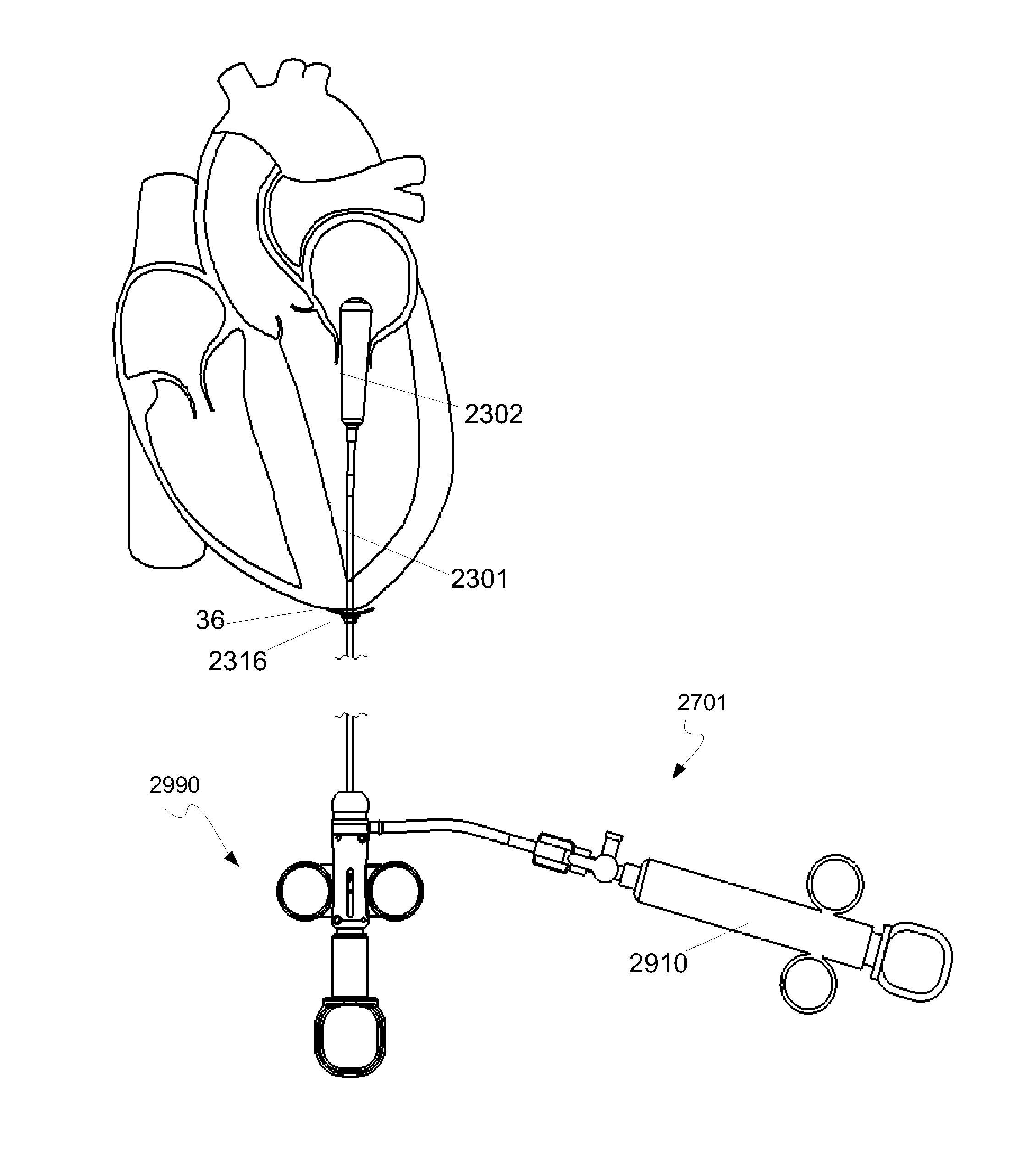
[0075]The present disclosure relates to a system and method of implanting a heart implant. For example, the system and method according to one embodiment of the present disclosure may be used to implant a heart valve implant which may suitably be used in connection with the treatment, diagnostics and / or correction of a dysfunctional or inoperative heart valve (e.g., function mitral valve regurgitation and degenerative mitral valve regurgitation). One suitable implementation for a heart valve implant consistent with the present disclosure is the treatment of mitral valve regurgitation (mitral insufficiency or mitral incompetence). For the ease of explanation, the heart valve implant herein is described in terms of a mitral valve implant, such as may be used in treating mitral valve regurgitation as described in U.S. patent application Ser. No. 11 / 258,828 filed Oct. 26, 2005 and U.S. patent application Ser. No. 12 / 209,686 filed Sep. 12, 2008, both of which are fully incorporated herei...


PUM


Abstract

A heart valve implant is disclosed herein. The heart valve implant comprises an inflatable valve body, a shaft, an anchor assembly and an inflation (injection) port. Also disclosed herein, are methods of trans-apically and trans-septally delivering a heart valve implant within a heart such that the valve body can be inflated in situ to partially or completely restrict blood flow through a heart valve in a closed position. The inflation (injection) port permits inflation of the valve body with an adjustable amount of an inflation fluid to attain a desired degree of inflation of the valve body when disposed within the heart valve.

Description

CROSS-REFERENCE AND RELATED APPLICATIONS[0001]The present application claims benefit of U.S. Provisional Patent No. 61 / 835,093, filed Jun. 14, 2013, the entire content of the application is hereby incorporated by reference.FIELD OF THE APPLICATION[0002]The present disclosure relates to the repair and / or correction of dysfunctional heart valves, and more particularly pertains to heart valve implants and systems and methods for delivery and implementation of the same.BACKGROUND[0003]The human heart has four chambers, the left and right atrium and the left and right ventricles. The chambers of the heart alternately expand and contract to pump blood through the vessels of the body. The cycle of the heart includes the simultaneous contraction of the left and right atria, passing blood from the atria to the left and right ventricles. The left and right ventricles then simultaneously contract forcing blood from the heart and through the vessels of the body. In addition to the four chambers...

Claims


Application Information

Patent Timeline
IPC IPC(8): A61F2/24
CPCA61F2/243A61F2/24A61F2250/0004A61F2250/0098A61F2250/0003A61F2/246A61F2/2466
Inventor WILSON, JONATHAN E.MURPHY, JOHNROBERTSON, JACKSEGUIN, CHRISTOPHER
Owner CARDIOSOLUTIONS
Why Eureka
Try Eureka