
Rear end collision prevention apparatus

a rear-end collision and apparatus technology, applied in the direction of road vehicle traffic control, vehicle components, instruments, etc., can solve the problems of affecting the safety of the driver, the safety of passengers, bystanders, and other individuals, and the number of rear-end collisions that cannot be prevented, so as to reduce or prevent rear-end collisions, reduce or prevent driver acclimatization

Inactive Publication Date: 2014-12-18
SEIFERT JERRY A
View PDF9 Cites 48 Cited by
  • Summary
  • Abstract
  • Description
  • Claims
  • Application Information

AI Technical Summary

Benefits of technology

The patent text describes a device that reduces rear end collisions on vehicles by alerting the driver to slow down or stop. It uses two types of lights: one to indicate a slow down or stop and another to indicate that the vehicle has not started re-accelerating after stopping or slowing down. This helps to keep the driver's attention on the road and reduces the risk of accidents. The device can be integrated into existing vehicles or used separately as a separate apparatus.

Problems solved by technology

All distractions compromise the safety of the driver, passengers, bystanders, and other individuals on the road.
The cost of lives, injuries and consequences related to these accidents are overwhelming.
However, the CHMSL and other types of third brake lights still did not prevent a majority of rear end collisions.
This reduces the effectiveness of CHMSL in preventing rear end collisions.
Unfortunately, this prior art reference does not provide a warning when a trailing vehicle is traveling too closely while maintaining a steady speed on the road.”
Unfortunately, this prior art reference employed in the existing brake lights may not adequately warn trailing drivers who are not familiar with the system and who may mistake the blinking lights as simply the driver tapping the breaks repeatedly.”
However, this prior art reference does not provide a light-emitting diode message display system that sequentially illuminates selected diodes for generating a warning message to more adequately warn the trailing vehicle.”

Method used


Image

  • Rear end collision prevention apparatus
  • Rear end collision prevention apparatus
  • Rear end collision prevention apparatus

Examples


Embodiment Construction

Rear End Collision Prevention Apparatus

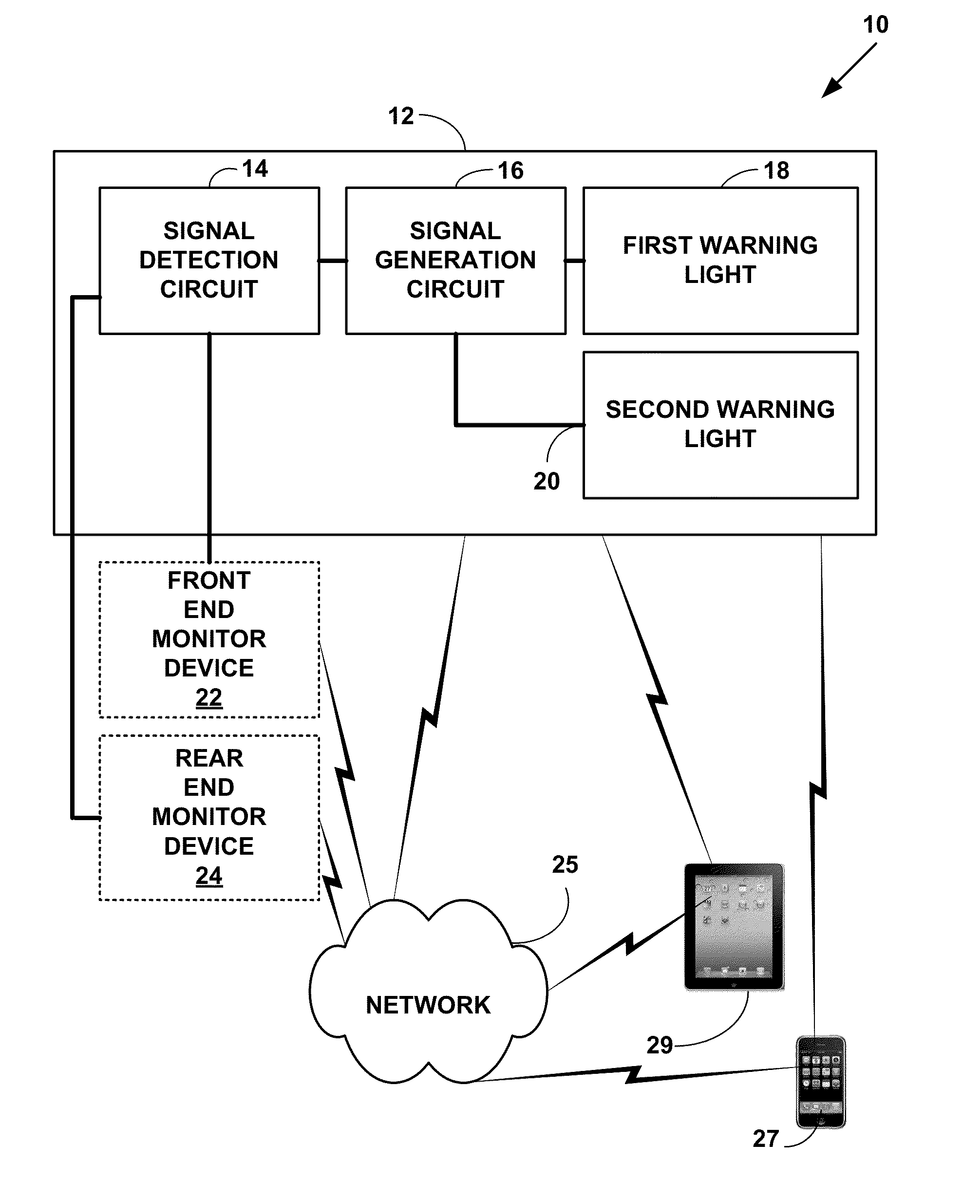
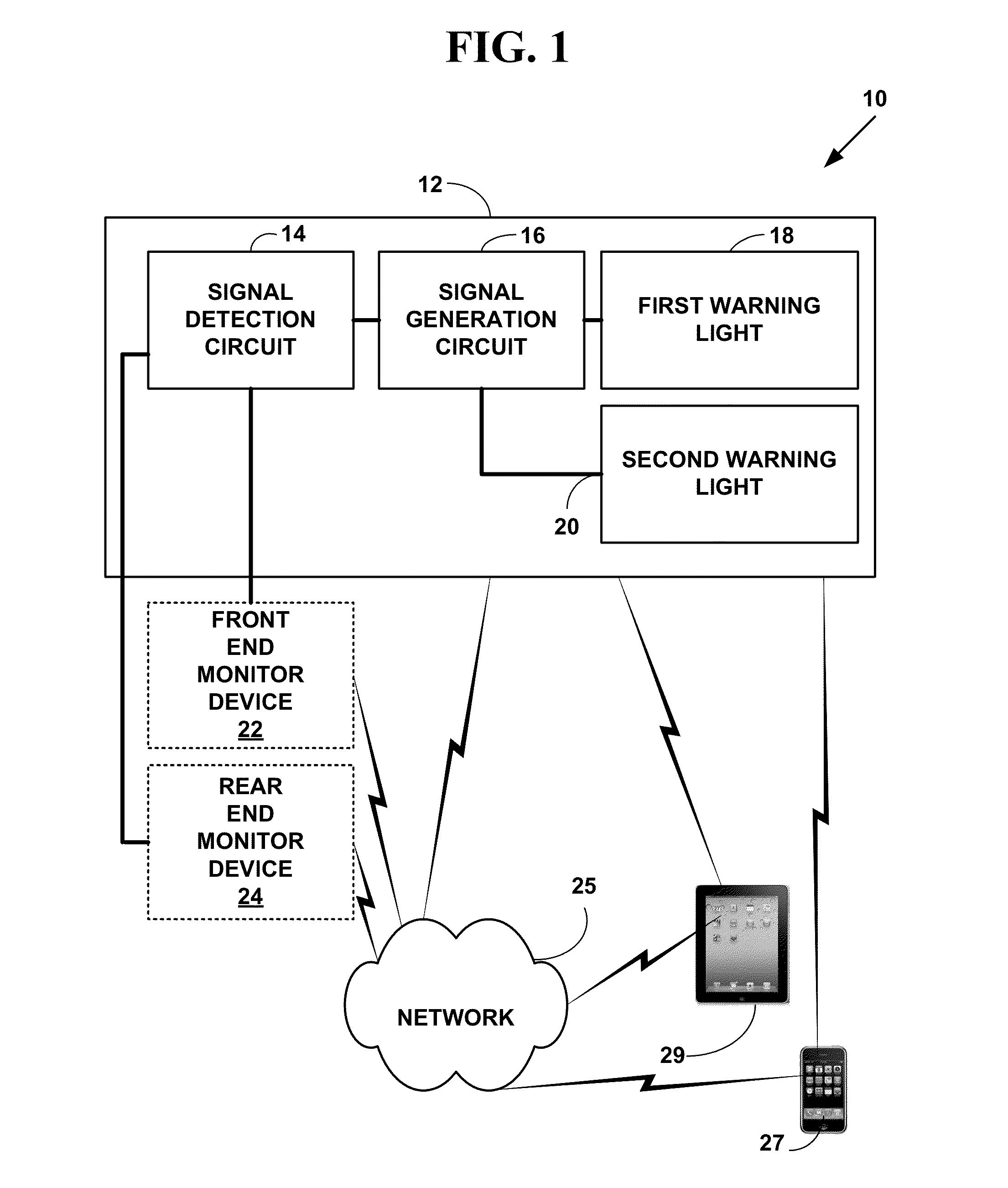
[0040]FIG. 1 is a block diagram 10 of a rear end collision prevention apparatus 12. The apparatus 12 includes a signal detection circuit 14, a signal generation circuit 16, a first warning light 18, a second warning light 20, connected to an optional front end monitor 22, and / or connected to an optional rear end monitor 24. However, the present invention is not limited to this embodiment and more, fewer, other and equivalent components can also be used to practice the invention.

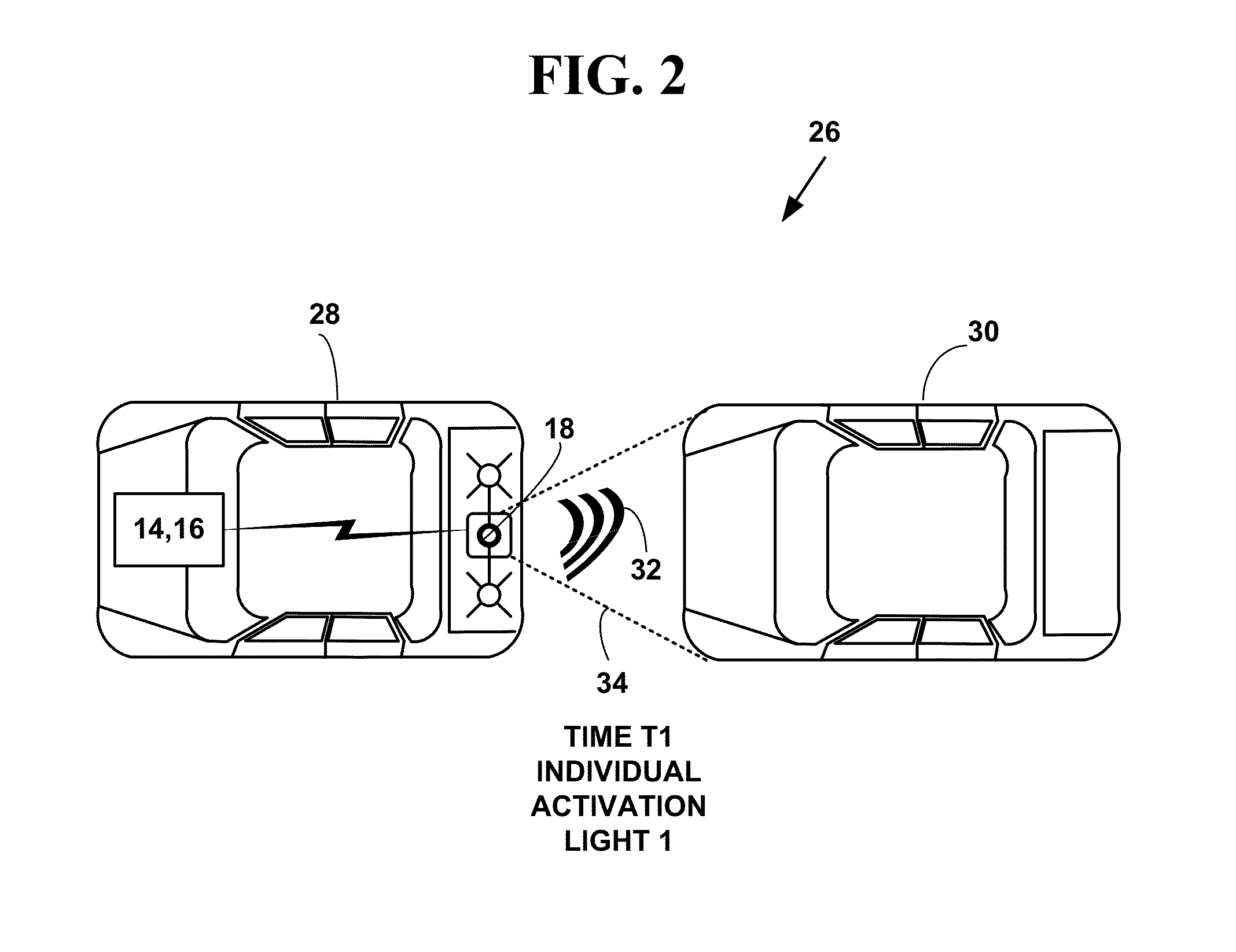
[0041]In one embodiment, the rear end collision apparatus 12 includes a wired device with a wired interface and / or a wireless device with a wireless interface to interface with a control system in a vehicle 28.

[0042]In one embodiment, the vehicle 28 includes a land vehicle (car, truck, motorcycle, bicycle, all terrain vehicle (ATV), etc.), marine vehicle (boat, ship, personal watercraft (e.g., jet ski, etc.), etc.), aviation vehicle (airplane, helicopter, etc.), space ve...


PUM


Abstract

A rear end collision apparatus. The rear end collision apparatus includes a first warning light to capture a driver's attention indicating a slow down or stop event is about to occur or is occurring and re-focuses a drivers' visual attention point and a different type of second warning light indicating the vehicle has not yet started re-accelerating after a slowing or stop event. The rear end collision prevention apparatus may be integrated into a Center High Mount Stop Lamp (CHMSL) on a vehicle or used as a separate apparatus. The read end collision apparatus helps reduce or prevent rear end collisions of vehicles and reducing or preventing driver acclimatization to warning lights in a CHMSL or other rear end collision warning lights.

Description

CROSS REFERENCES TO RELATED APPLICATIONS[0001]This U.S. Utility patent application claims priority to U.S. Provisional patent application number No. 61 / 668,502, filed Jul. 6, 2012, the contents of which are incorporated by reference.FIELD OF THE INVENTION[0002]This invention relates to preventing vehicle accidents. More specifically, it relates to a rear end collision prevention apparatus.BACKGROUND OF THE INVENTION[0003]“Distracted driving” is driving while engaged in other activities—such as using a cell phone, texting, eating, or reading—which take the driver's attention away from the road. Distractions while driving can be separated into three distinct groups: visual, manual, and cognitive. “Visual distraction” involves taking one's eyes off the road. “Manual distraction” involves taking one's hands off the wheel. “Cognitive distraction” occurs when an individual takes their mind off of driving. All distractions compromise the safety of the driver, passengers, bystanders, and ot...

Claims


Application Information

Patent Timeline
Patent Type & Authority Applications(United States)
IPC IPC(8): B60Q9/00G08G1/16
CPCG08G1/166B60Q9/008B60Q1/302B60Q1/444B60Q1/46B60Q1/535
Inventor SEIFERT, JERRY A.
Owner SEIFERT JERRY A
Learn More