Cable hook attachment for ladders

a technology of cable hooks and ladders, applied in the field of cable hooks, can solve the problems of ladder movement, falling, falling, falling, etc., and achieve the effect of improving user safety and improving safety

Active Publication Date: 2014-12-18
BOLINSKI ERIC C
View PDF29 Cites 16 Cited by
  • Summary
  • Abstract
  • Description
  • Claims
  • Application Information

AI Technical Summary

Benefits of technology

[0023]A fixed strand grabber and a removable strand grabber are presented for use on a conventional ladder. The strand grabber includes a hook member connected to a top pivoting arm or other support and a bottom lever. The bottom lever has a portion that extends past and encloses the open interior of the hook. The hook protrudes from the forward side of a ladder. As the ladder is lowered over a cable, the cable causes the hook to move upward which in turn causes the bottom lever to rotate upward. A portion of the bottom lever encloses the open interior of the hook thereby locking the cable therein. In this way improved safety is provided as the cable is prevented from accidently slipping out of the open interior of the hook which improves user safety. The system also provides an attachment point for a safety lock. In addition, the removable strand grabber provides a V-brace for using against utility poles.

Problems solved by technology

Because ladders are used to provide access high above the ground, safety is a preeminent issue.
One particularly treacherous situation includes when a ladder is used by propping it up against a wire, cord or cable which is stretched in space such as a telephone cable, power line or the like (collectively referred hereinafter as “cable”).
This situation is particularly dangerous because the cable is dynamic in nature.
This can cause the ladder to move, fall slip or slide itself.
In addition, there is no mechanism holding the cable within the hook other than the force of gravity.
In addition, these cable hooks have a tendency to get in the user's way when not in use and therefor pose a safety problem.
In addition, when engaged, this cross bracket is in the primary operating space of the user which is hazardous and reduces the utility of the device.
Furthermore this device is heavy and bulky, which are substantial problems when a device is used in association with a ladder and is used high above the ground.

Method used


Image

  • Cable hook attachment for ladders
  • Cable hook attachment for ladders
  • Cable hook attachment for ladders

Examples


Embodiment Construction

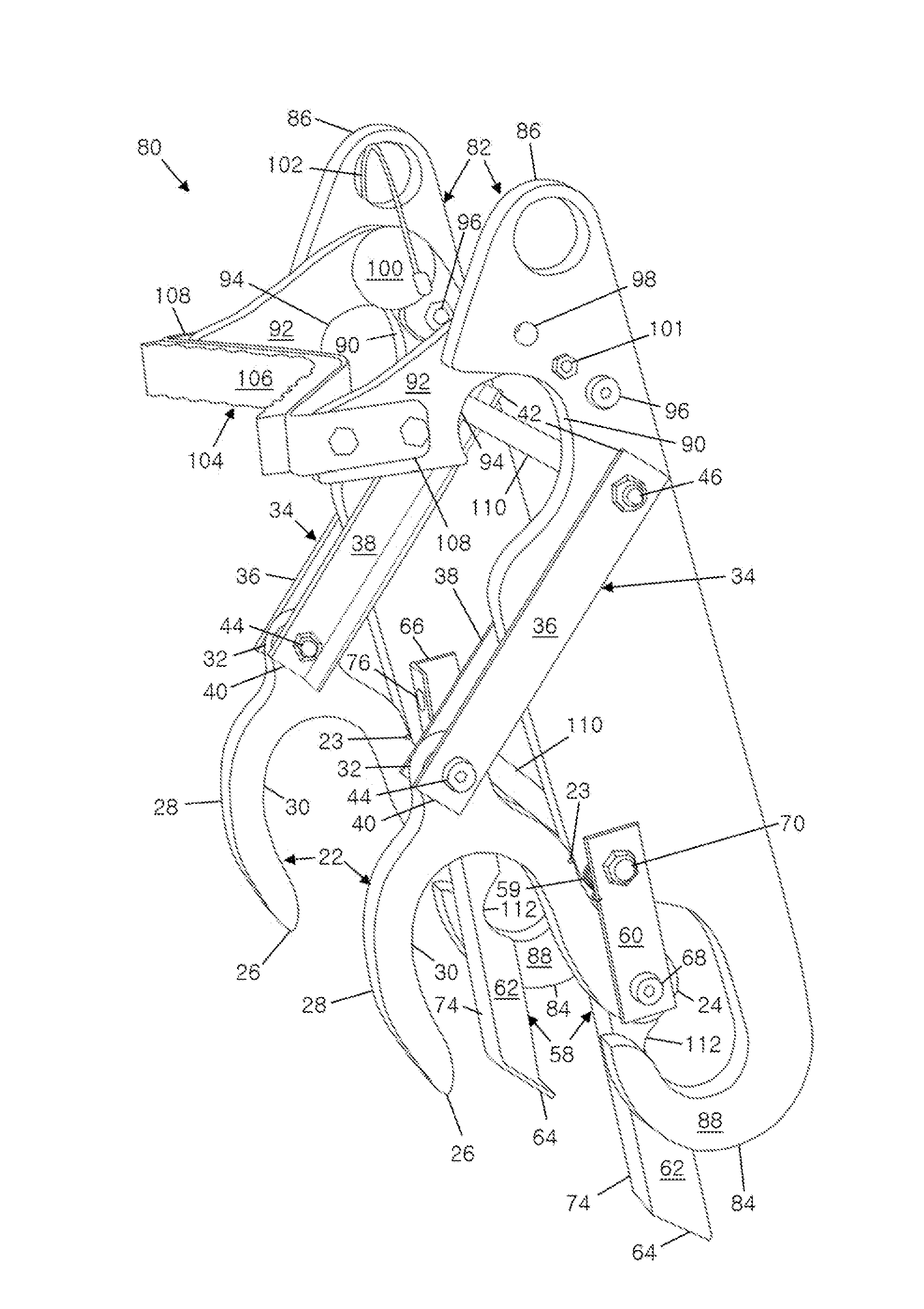
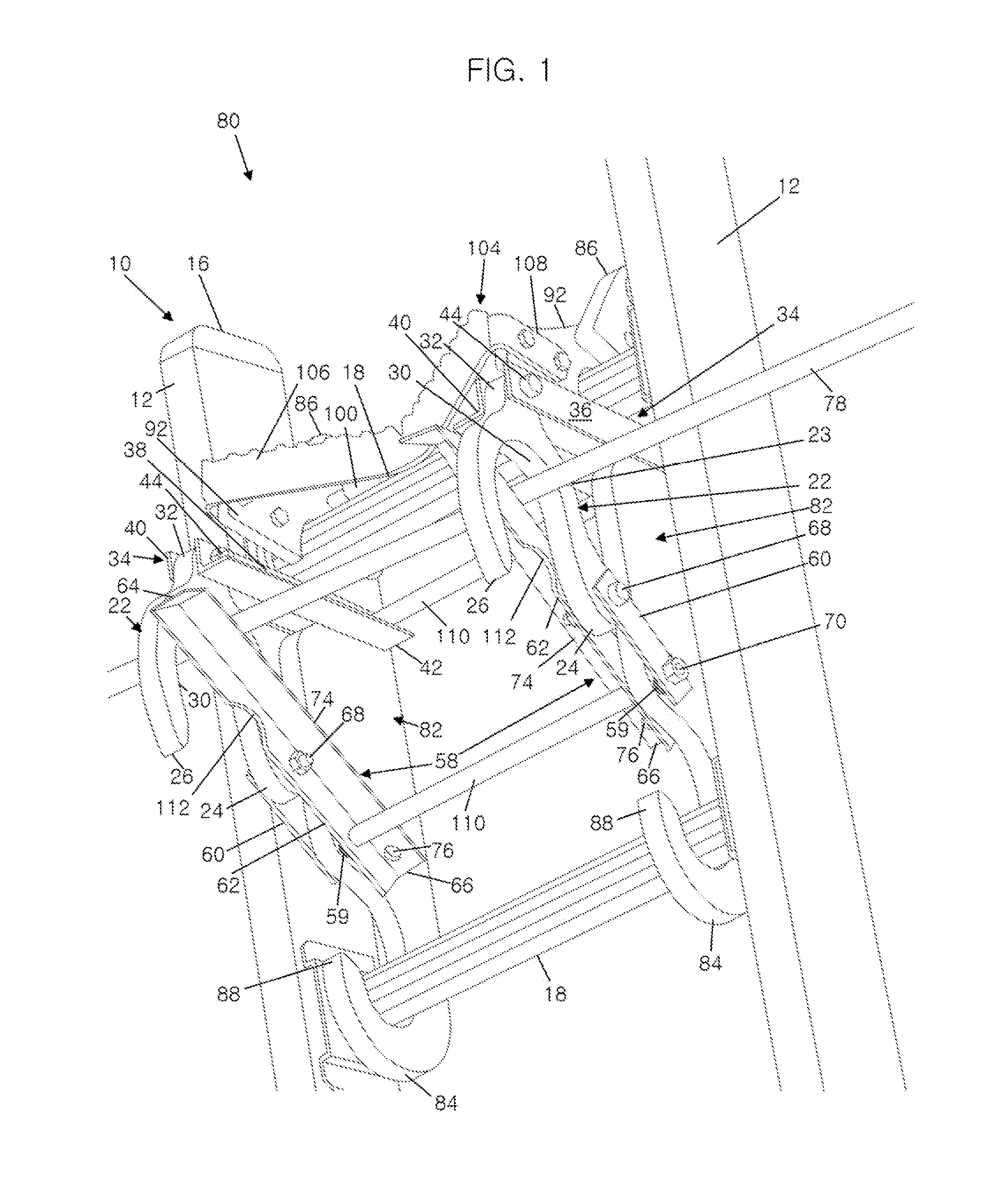
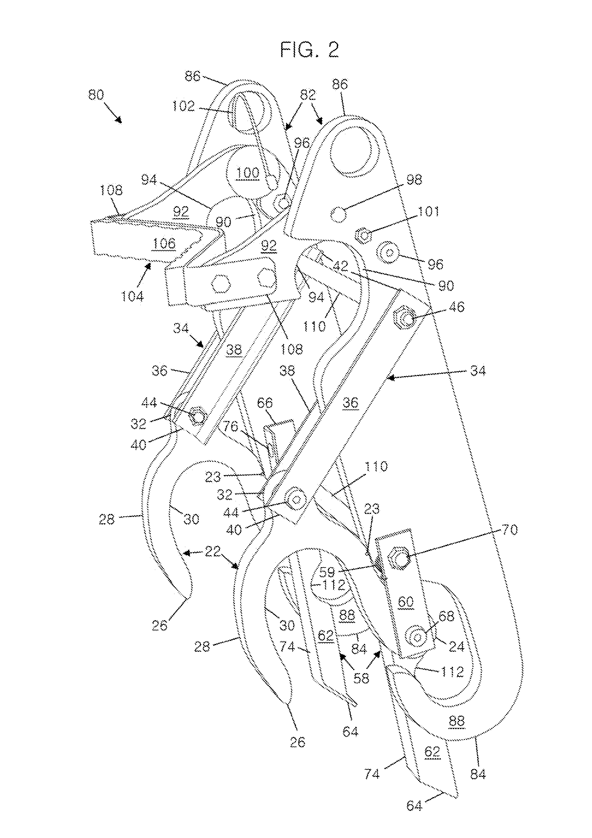
[0033]In the following detailed description, reference is made to the accompanying drawings which form a part hereof, and in which is shown by way of illustration specific embodiments in which the invention may be practiced. These embodiments are described in sufficient detail to enable those skilled in the art to practice the invention, and it is to be understood that other embodiments may be utilized and that mechanical, procedural, and other changes may be made without departing from the spirit and scope of the present inventions. The following detailed description is, therefore, not to be taken in a limiting sense, and the scope of the present invention is defined only by the appended claims, along with the full scope of equivalents to which such claims are entitled.

[0034]As used herein, the terminology such as vertical, horizontal, top, bottom, front, back, ends, sides, etc., are referenced according to the views presented. It should be understood, however, that the terms are u...


PUM


Abstract

A fixed strand grabber and a removable strand grabber are presented for use on a conventional ladder. The strand grabber includes a hook member connected to a top support and a bottom lever. The bottom lever has a portion that extends past and encloses the open interior of the hook that protrudes from the forward side of the ladder. As the ladder is lowered over a cable, the hooks move upward which in turn causes the bottom lever to rotate upward. A portion of the bottom lever encloses the open interior of the hook thereby locking the cable therein. In this way improved safety is provided as the cable is prevented from accidently slipping out of the open interior of the hook which improves user safety. The system also provides an attachment point for a safety lock. In addition, the removable strand grabber provides a V-brace for using against utility poles.

Description

CROSS REFERENCE TO RELATED APPLICATION[0001]This application claims the benefit of U.S. Provisional Application No. 61 / 836,305 filed Jun. 18, 2013.FIELD OF THE INVENTION[0002]This invention relates to a cable hook. More specifically, and without limitation, this invention relates to a cable hook attachment for ladders.BACKGROUND OF INVENTION[0003]Ladders are old and well known in the art. Conventional ladders have a pair of laterally extending side rails that extend in parallel spaced relation to one another a distance. A plurality of transverse rungs extend across and between connecting the opposing side rails. Ladders are often used by placing one end of the ladder on the ground and positioning the opposite end on the side of a building or structure such that the ladder extends upwardly at an angle. In this position, a user climbs the ladder by grasping the rungs and / or the side rails while incrementally stepping on the rungs. In this way ladders are used to access areas high abov...

Claims


Application Information

Patent Timeline
Patent Type & Authority Applications(United States)
IPC IPC(8): E06C7/18
CPCE06C7/188E06C7/48
Inventor BOLINSKI, ERIC C.STONER, RICHARD B.
Owner BOLINSKI ERIC C
Why Eureka
Try Eureka