Information processor and program
a technology applied in the field of information processor and program, can solve problems such as accidental application of force, and achieve the effect of a new, highly portable information processor
- Summary
- Abstract
- Description
- Claims
- Application Information
AI Technical Summary
Benefits of technology
Problems solved by technology
Method used
Image
Examples
embodiment 1
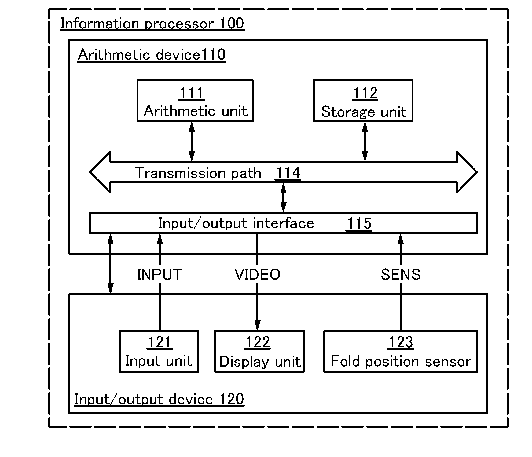
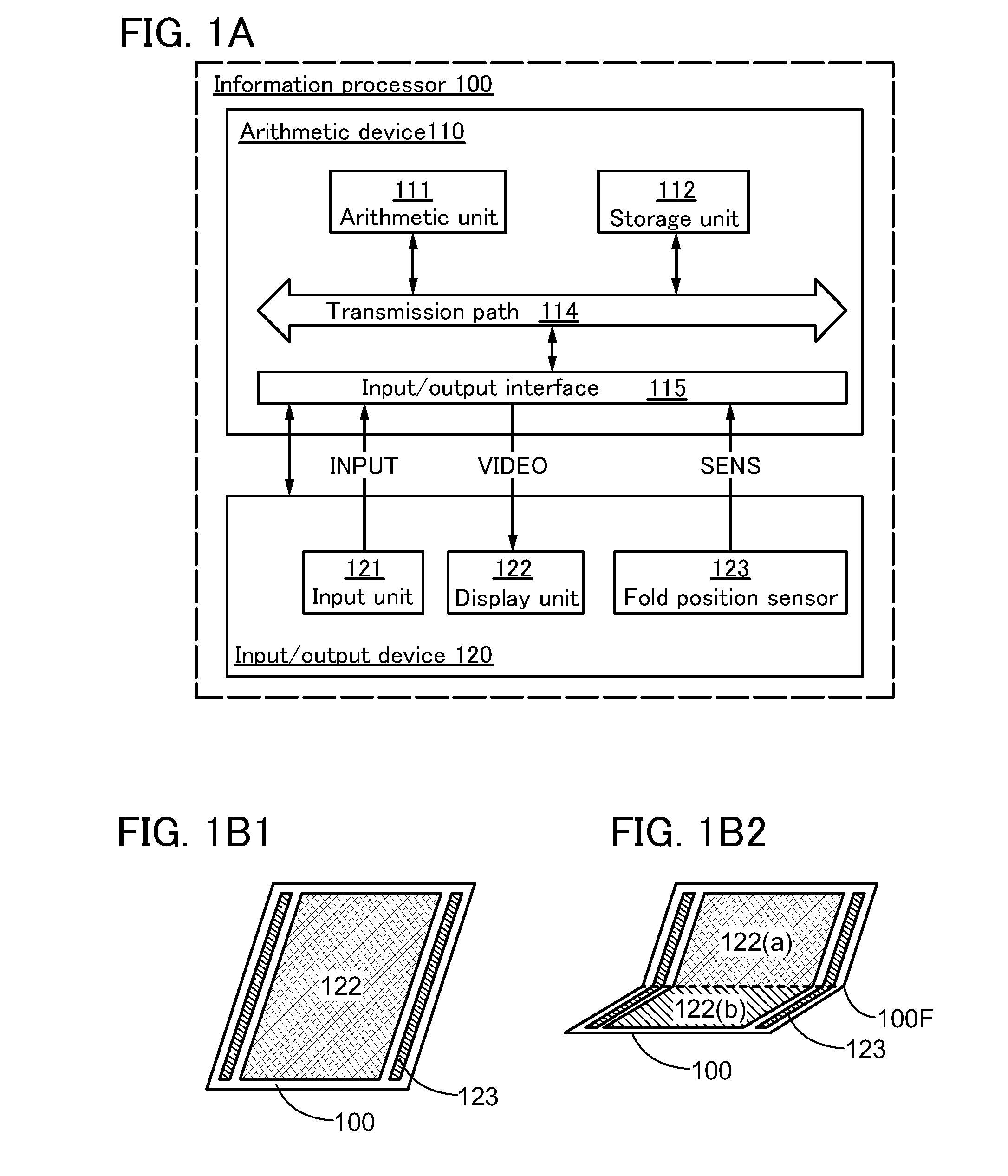
[0038]In this embodiment, a structure of an information processor of one embodiment of the present invention will be described with reference to FIGS. 1A, 1B1, and 1B2, FIGS. 2A and 2B, and FIG. 3.
[0039]FIG. 1A is a block diagram illustrating the structure of the information processor of one embodiment of the present invention.
[0040]FIGS. 1B1 and 1B2 are schematic views illustrating the structure of the information processor of one embodiment of the present invention. FIG. 1B2 is a schematic view illustrating the information processor in FIG. 1B1 in a bent state.
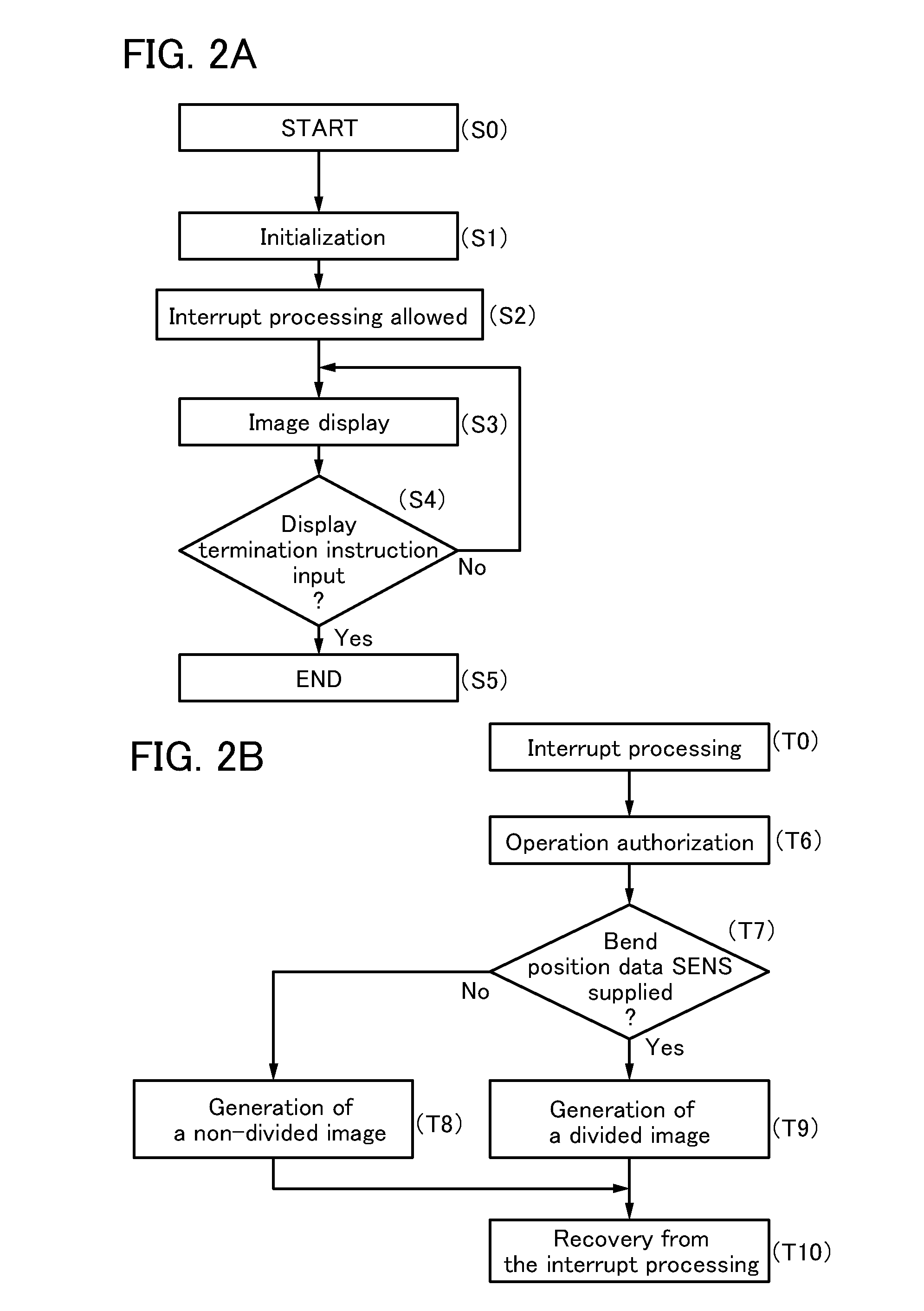
[0041]FIGS. 2A and 2B are flow charts illustrating a program to be executed by an arithmetic unit of the information processor of one embodiment of the present invention.
[0042]FIG. 3 is a flow chart showing a modification example of the program to be executed by the arithmetic unit of the information processor of one embodiment of the present invention.
[0043]An information processor 100 described in this embodiment includes ...
modification example 2
[0102]An information processor that is shown as Modification Example 2 in this embodiment will be described with reference to FIGS. 6A, 6B1, and 6B2.
[0103]FIGS. 6A, 6B1, and 6B2 are a flow chart and schematic views showing a modification example of the program to be executed by the arithmetic unit 111 of the information processor of one embodiment of the present invention.
[0104]The information processor shown as Modification Example 2 in this embodiment differs from the information processor described with reference to FIGS. 2A and 2B in the interrupt processing of the program to be executed by the arithmetic unit 111. Thus, different portions will be described in detail below. Refer to the above description for portions where the same structures can be employed.
[0105]In Modification Example 2 in this embodiment, the program includes the following interrupt processing instead of the above-described interrupt processing. In a sixth step, a display termination instruction and bend pos...
embodiment 2
[0118]In this embodiment, an information processor of one embodiment of the present invention will be described with reference to FIGS. 4A, 4B, 4C, 4D1, and 4D2.
[0119]FIG. 4A is a plan view illustrating a structure of an information processor 200 of one embodiment of the present invention, and FIG. 4B is a side view illustrating the structure of the information processor 200. Note that the arrows in the drawings indicate the side where display is performed.
[0120]FIG. 4C is a side view illustrating a structure of part of a bending member 281 illustrated in FIG. 4A.
[0121]FIGS. 4D1 and 4D2 are side views illustrating examples in which a display unit 222 is divided into two regions at the position where an input / output device 220 is bent.
[0122]The information processor 200 includes an arithmetic device 210 that receives bend position data and an operation instruction and supplies image data. The information processor 200 also includes the input / output device 220 that receives image data...
PUM
 Abstract
Description
Claims
Application Information
 - R&D
- Intellectual Property
- Life Sciences
- Materials
- Tech Scout
- Unparalleled Data Quality
- Higher Quality Content
- 60% Fewer Hallucinations
Browse by: Latest US Patents, China's latest patents, Technical Efficacy Thesaurus, Application Domain, Technology Topic, Popular Technical Reports.
© 2025 PatSnap. All rights reserved.Legal|Privacy policy|Modern Slavery Act Transparency Statement|Sitemap|About US| Contact US: help@patsnap.com


