
Magnetic resonance multi-core array radio frequency device and magnetic resonance signal receiving method

a multi-core array and radio frequency technology, applied in the field of magnetic resonance radio frequency, can solve the problems of reducing the workload of the receiving system, reducing the cost of the whole receiving system, and reducing the redundancy of the circuit, so as to reduce the workload and reduce the cost

Active Publication Date: 2014-12-11
SHENZHEN INST OF ADVANCED TECH CHINESE ACAD OF SCI
View PDF5 Cites 23 Cited by
  • Summary
  • Abstract
  • Description
  • Claims
  • Application Information

AI Technical Summary

Benefits of technology

The patent describes a device and method for magnetic resonance imaging (MRI) that uses a single device to select different radio frequency coil channels and filters based on the needs of different magnetic resonance nucleuses. This eliminates the need for separate circuits for each nucleus, reducing costs and complexity. The technical effect of this invention is improved efficiency and reduced cost for magnetic resonance imaging.

Problems solved by technology

This manner reduces the workload of the receiving system, while leaves a great redundancy on the signal processing ability of the receiving system.
When the channels increase to a certain number, such simple repeatedly received circuit will make the whole receiving system extremely expensive and cumbersome.

Method used


Image

  • Magnetic resonance multi-core array radio frequency device and magnetic resonance signal receiving method
  • Magnetic resonance multi-core array radio frequency device and magnetic resonance signal receiving method
  • Magnetic resonance multi-core array radio frequency device and magnetic resonance signal receiving method

Examples


Embodiment Construction

[0021]The invention will be described in detail with the following embodiments and drawings.

[0022]Referring to FIG. 1, in an embodiment, a magnetic resonance multi-core array radio frequency device includes a radio frequency receiver and a radio frequency transmitter.

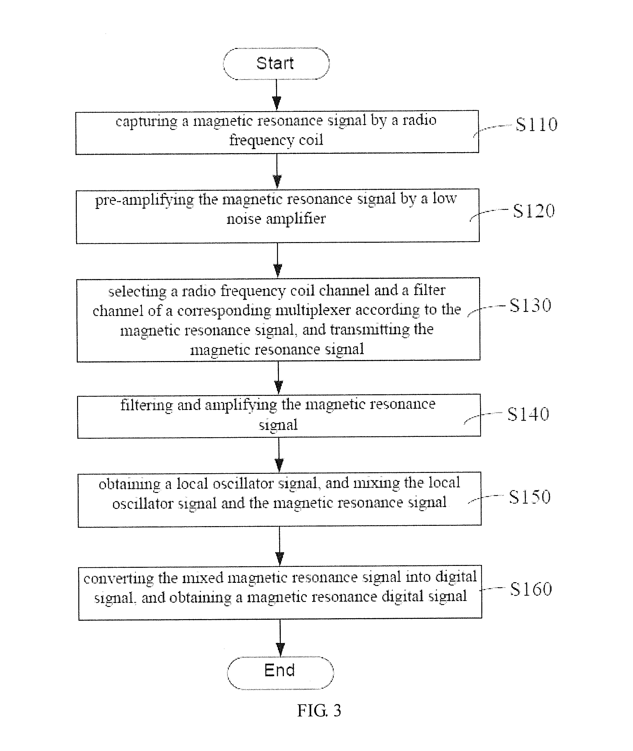
[0023]The radio frequency receiver includes a plurality of radio frequency coils 11, a low noise amplifier 13, a multiplexer 15, a radio frequency band-pass filter 17, a programmable gain amplifier 19, a frequency synthesizer 21, a mixer 23, an intermediate frequency band-pass filter 25, a general amplifier 27, an A / D converter 29, and a controller 31.

[0024]The radio frequency coils 11 are configured to capture a magnetic resonance signal.

[0025]In the illustrated embodiment, the radio frequency coils 11 are receiving and transmitting terminals of the magnetic resonance multi-core array radio frequency device. The radio frequency coils 11 may be multichannel phased array coils, combined coils, or body coils. Alternativel...


PUM


Abstract

A magnetic resonance multi-core array radio frequency device and a magnetic resonance signal receiving method are provided. The device comprises a radio frequency receiver which includes a radio frequency coil (11), a low noise preamplifier (13), a multiplexer (15), a radio frequency band-pass filter (17), a program control amplifier (19), a frequency synthesizer (21), a mixer (23), an analog to digital converter (29) and a controller (31). The controller (31) is used for controlling the multiplexer (15) to select a corresponding radio frequency coil channel, a corresponding filtering channel, gain of the radio frequency band-pass filter (17), and receiving a magnetic resonance digital signal transmitted by the analog to digital converter (29). Due to the multiplexer (15), there is no need to configure different circuits respectively for different nuclear magnetic resonance, redundancy of the circuits is reduced, and cost is reduced.

Description

FIELD OF THE INVENTION[0001]The present invention relates to a field of magnetic resonance radio frequency, and more particularly relates to a magnetic resonance multi-core array radio frequency device and a magnetic resonance signal receiving method.BACKGROUND OF THE INVENTION[0002]A radio frequency device is an important component of the magnet resonance imaging equipment. It excites polarized nucleuses (such as 1H, 19F) in an object using radio frequency pulses transmitted by different radio frequency pulse sequences, so as to generate a plurality of magnetic resonance (MR) signals, and receive the MR signals.[0003]Classified by functions, the radio frequency device includes radio frequency receiver and radio frequency transmitter. The radio frequency receiver is generally composed of a plurality of circuit units, such as receiving coil, preamplifier, local oscillator, mixer, filter, A / D converter (analog to digital converter), modem, and coupler, etc; the radio frequency transmi...

Claims


Application Information

Patent Timeline
Patent Type & Authority Applications(United States)
IPC IPC(8): G01R33/36
CPCG01R33/3621G01R33/3628G01R33/3614G01R33/3415G01R33/3664
Inventor QIU, BENSHENGSONG, YIBIAOZHANG, YONGQINMIAO, HUILIU, XINZHENG, HAIRONG
Owner SHENZHEN INST OF ADVANCED TECH CHINESE ACAD OF SCI
Learn More