
Computer based ballot system and process

a computer-based and ballot-based technology, applied in the field of computer-based ballot-based system and apparatus, can solve the problems of cumbersome and expensive current ballot-based systems, limited how often ballots can be carried out, and require a lot of manual effort, so as to facilitate the operation of ballots

Inactive Publication Date: 2014-11-27
DOSHMOSH
View PDF2 Cites 10 Cited by
  • Summary
  • Abstract
  • Description
  • Claims
  • Application Information

AI Technical Summary

Benefits of technology

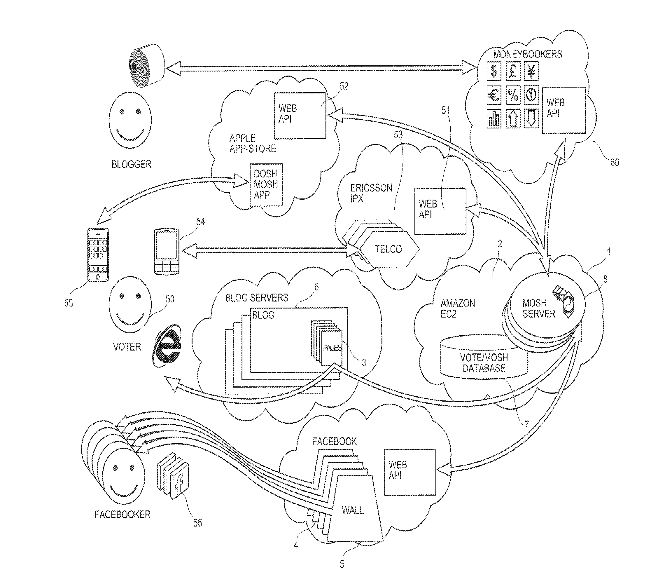
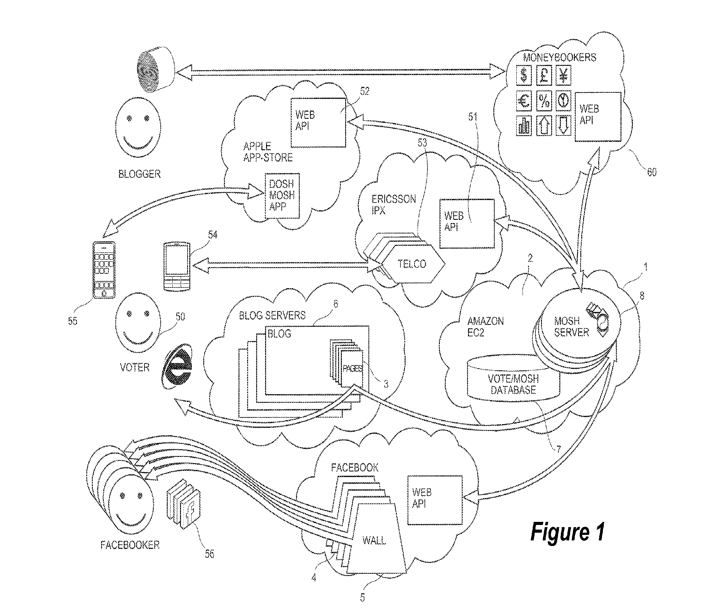
The present invention provides a computer-based ballot system that allows users to easily create and vote on virtual ballots. The system uses tags to represent different things, such as contexts and subjects, and helps connect them together in a way that makes sense. The system also analyzes voting behaviors to better understand what people are doing when they are using the system. Additionally, the system can associate a user's location with a ballot or a specific subject to make the voting process more personal. Overall, this invention helps streamline the voting process and make it easier for people to have their voices be heard.

Problems solved by technology

Current balloting systems, however, are cumbersome and very expensive.
These still require an intense manual effort.
Because of the expense and effort required, there are limitations on how often ballots can be carried out.
Another issue with current systems is the “one person one off vote” approach.
Because of these limitations to conventional balloting, therefore, there are necessary limitations on the democratic input that a society's population can have in a democracy.
The number of issues that a single voter is able to cast their vote on is very limited.
The chance to vote in ballots on particular issues is extremely limited, if available at all (eg referendum).
Apart from counting the number of hits on these Websites there is no reliable way of assessing the success or otherwise of an article or comment on a particular issue, nor of assessing the preferences regarding this issue of users of a plurality of Websites.
Further, revenue for such sites is generally restricted to registration fees and / or advertising.

Method used


Image

  • Computer based ballot system and process
  • Computer based ballot system and process
  • Computer based ballot system and process

Examples


example

[0400]Note that in this example, the terminology “DoshMosh” refers to a system in accordance with an embodiment of the present invention.

[0401]In the above embodiment, the system is shown with network interfaces based on the Worldwide Web. The system is not limited to this, any network architecture may be used to implement embodiments of the present invention and it is not limited to the Internet.

[0402]In the above embodiment, the system is implemented via the Internet. The system is not limited to this. Embodiments may be implemented by other Wide Area Networks, or Closed Area Networks. Other networks may be connected into the system in addition to the Internet, for example. A closed network or intranet may implement an interface (eg API) to the host computing process utilizing applications operating in the closed intranet eg implementing voting interfaces using different computer software / hardware than that used in the external network. Other variations are possible.

[0403]It will...


PUM


Abstract

The present invention relates to a computer based ballot system and apparatus enabling polling to be implemented by Wide Area Networks, such as the Internet. A user is able to cast a vote utilising a voting device in the form of a computing process, via a voting interface, which may be a distributed computing element, distributed by webpages. Persons may be able to place votes relating to the content of various webpages. Ballots are generated as a plurality of linked ballots, and when a vote is placed on one ballot the vote may propagate through the other ballots that are linked to it. The structure of the linkage between the ballots may be determined based on user input.

Description

FIELD OF THE INVENTION[0001]The present invention relates to an improved computer based ballot system and apparatus and, particularly, but not exclusively, to a ballot system and apparatus enabling polling to be implemented via Wide Area Networks, such as the Internet.[0002]The contents of the applicant's earlier filed International (PCT) Patent Application No. PCT / AU2011 / 000761 entitled “a computer based ballot system and process” and filed on 24 Jun. 2011, claiming priority from Australian Patent Application No. 2010902810 (priority date 25 Jun. 2010), is herein incorporated in its entirety.BACKGROUND OF THE INVENTION[0003]In any democracy, the ability to ballot a population is an absolute requirement. Current balloting systems, however, are cumbersome and very expensive. The majority of existing ballot systems are still, for the most part, manually implemented.[0004]Partly electronic systems are known where manually marked ballot papers are partially counted electronically. These...

Claims


Application Information

Patent Timeline
IPC IPC(8): G07C13/00H04W4/02H04W4/021
CPCG07C13/00H04W84/042H04W4/021G06Q30/02G06Q50/01
Inventor MEREL, PETER ALEXANDER
Owner DOSHMOSH
Learn More