Eureka AIR delivers breakthrough ideas for toughest innovation challenges, trusted by R&D personnel around the world.

Developer controlled layout

a developer and layout technology, applied in the field of graphics processing, can solve the problems of cpu overhead, system not fully utilizing the processing power of the gpu, developer has no control over the design of the data layout,

Active Publication Date: 2014-11-27
SONY COMPUTER ENTERTAINMENT INC
View PDF6 Cites 20 Cited by
  • Summary
  • Abstract
  • Description
  • Claims
  • Application Information

AI Technical Summary

Benefits of technology

This patent is about a method and system for compiling instructions for a GPU program. Other languages, like C, can be used to define the layout of resources for the program, which are then translated into a specific language for the GPU. This allows for better performance and efficiency when running the program on a GPU. Overall, the patent aims to improve the development and performance of GPU programs.

Problems solved by technology

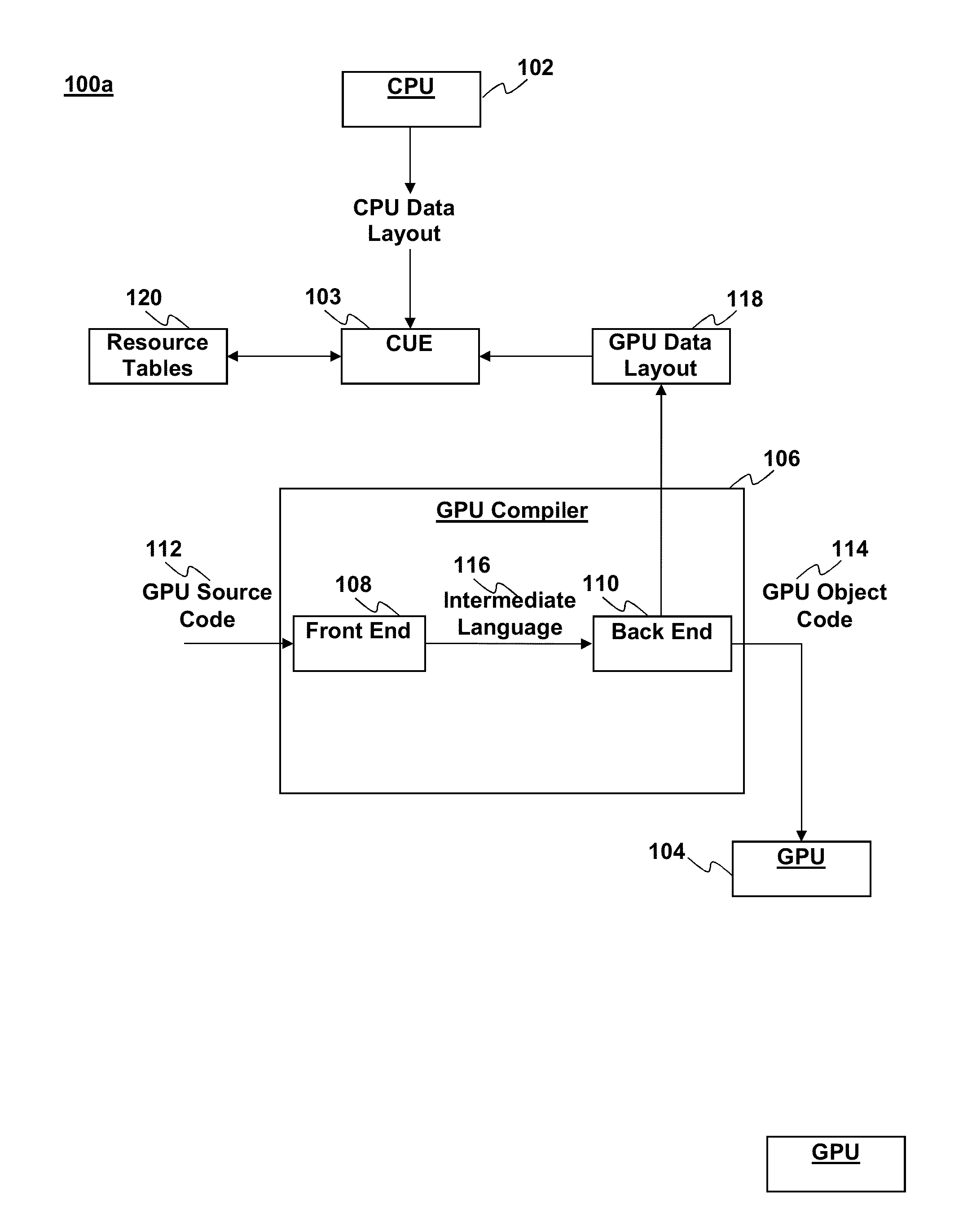
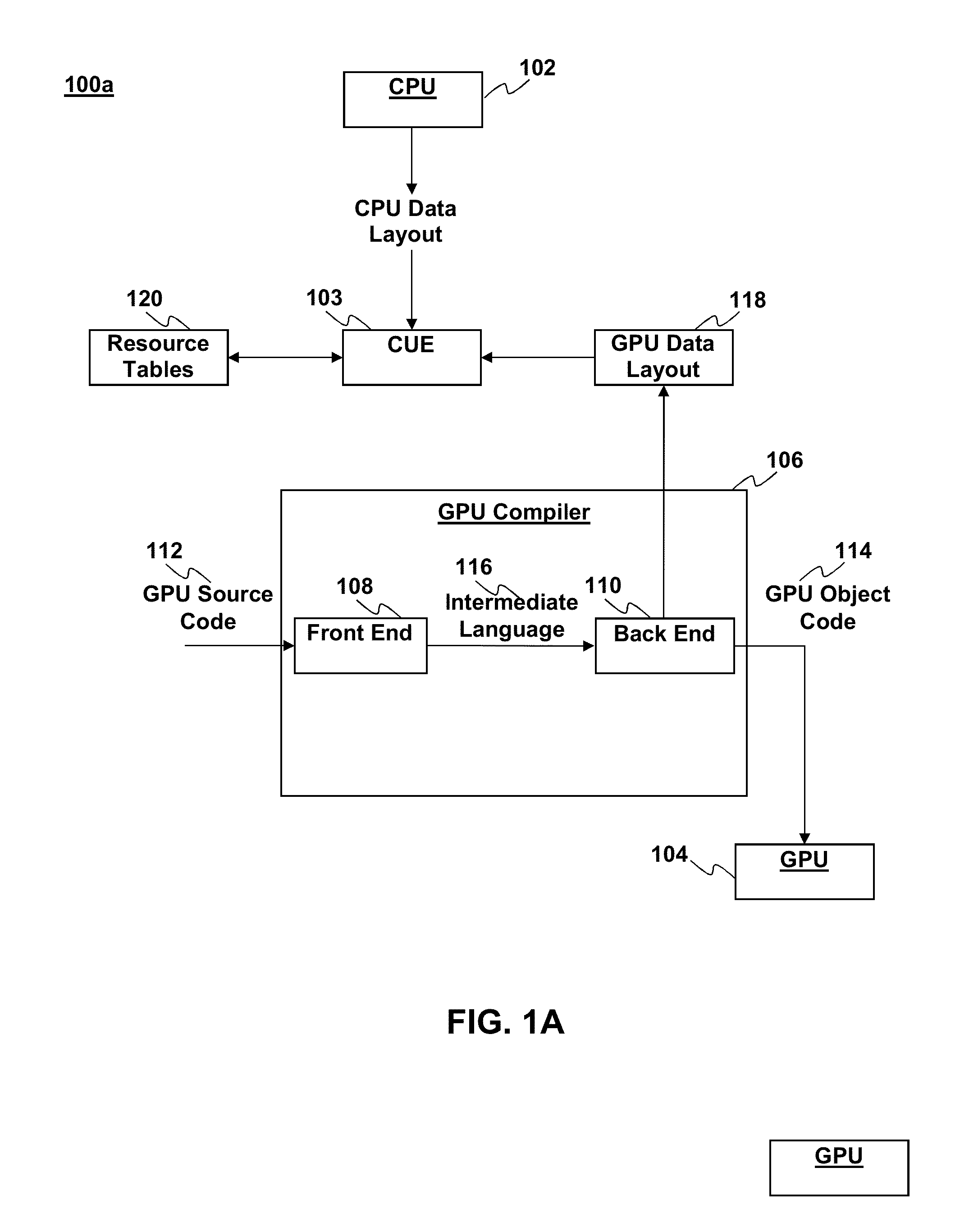
One drawback with such a setup is that the layout 118 of resources for the GPU programs is dictated by the back end 110 of the compiler 106 in a way that may be inefficient.
Moreover, the large amount of overhead and bookkeeping associated with this constant CPU-GPU interaction can create a bottleneck and prevent the system from fully utilizing the GPU's processing power.
The CPU overhead is partly a result of the way graphics processing systems handle memory access from a graphics pipeline.
However, even in such systems the developer has no control over the design of the data layout, which is dictated by part of the GPU compiler.
It may be impractical (or too expensive) to implement a high latency, low bandwidth bus.

Method used


Image

  • Developer controlled layout
  • Developer controlled layout
  • Developer controlled layout

Examples


Embodiment Construction

[0026]Although the following detailed description contains many specific details for the purposes of illustration, anyone of ordinary skill in the art will appreciate that many variations and alterations to the following details are within the scope of the invention. Accordingly, the exemplary embodiments of the invention described below are set forth without any loss of generality to, and without imposing limitations upon, the claimed invention.

[0027]In light of the aforementioned overhead and frequent CPU-GPU interaction, it would be desirable to provide increased control to developers and programmers of applications implementing graphics processing using modern hardware architectures. Because developers of the programs typically have the best knowledge of which data is used frequently and the best way to lay out data for applications running on CPUs, as well as associated GPU programs that render their corresponding graphics, it would be desirable to provide a mechanism that allo...


PUM


Abstract

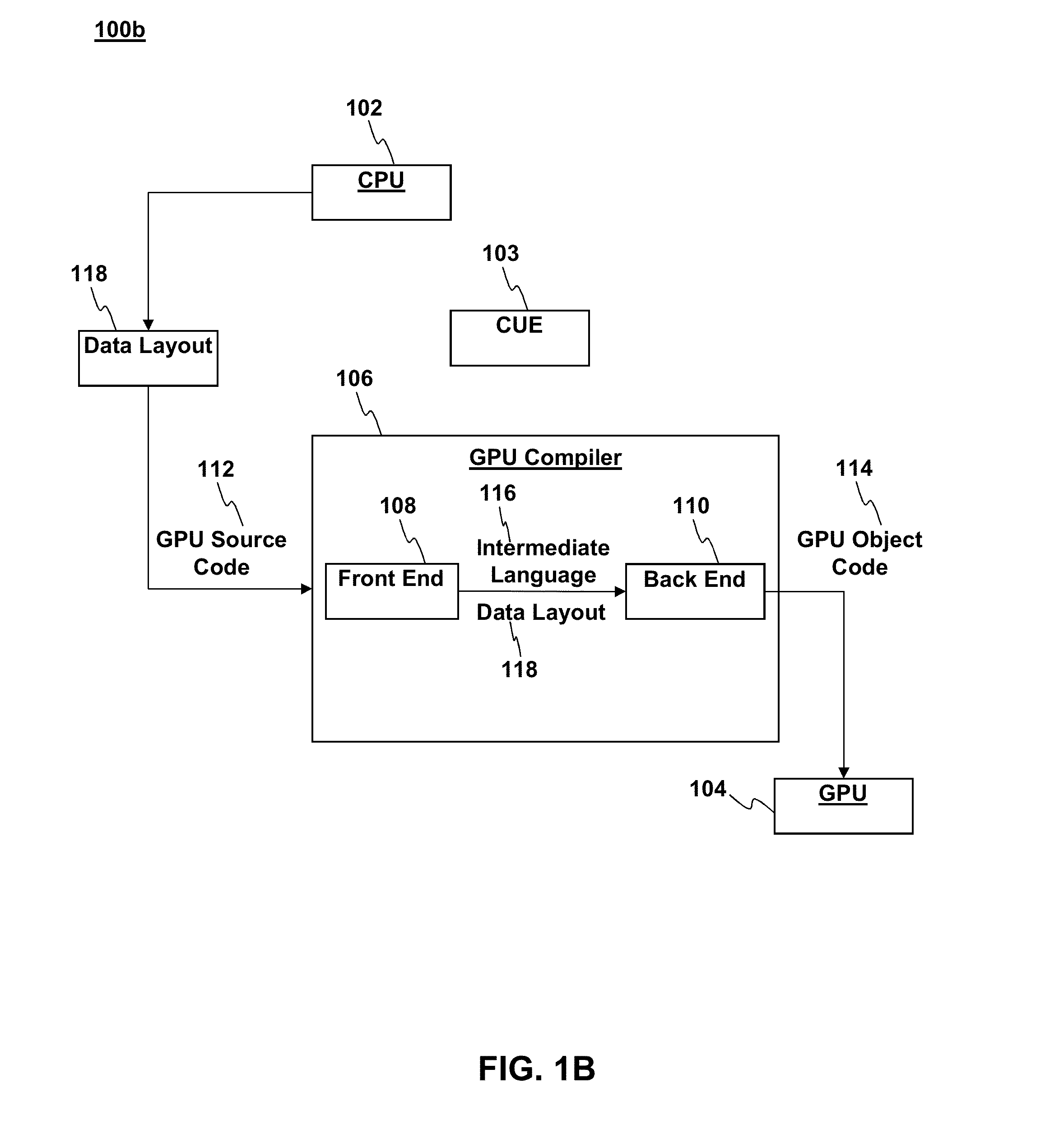
A method for processing graphics for a GPU program, translating instructions from a shading language into an intermediate language with a front end of a GPU compiler; translating the instructions from the intermediate language into a GPU object language with a back end of the GPU compiler; wherein the instructions in the shading language include instructions defining a layout of resources for the GPU program.

Description

FIELD OF THE DISCLOSURE[0001]The present disclosure relates to graphics processing. More specifically, the present disclosure relates to a developer controlled layout of shader resources for a program that can implemented by a graphics processing unit (GPU).BACKGROUND[0002]Graphics processing typically involves coordination of two processors, a central processing unit (CPU) and a graphics processing unit (GPU). The GPU is a specialized electronic circuit designed to accelerate the creation of images in a frame buffer intended for output to a display. GPUs are used in embedded systems, mobile phones, personal computers, workstations, and game consoles. A GPU is typically designed to be efficient at manipulating computer graphics. GPU's often have a highly parallel processing architecture that makes the GPU more effective than a general-purpose CPU for algorithms where processing of large blocks of data is done in parallel.[0003]The CPU may send commands to the GPU to implement a part...

Claims


Application Information

Patent Timeline
IPC IPC(8): G06T1/20
CPCG06T1/20
Inventor STENSON, RICHARD B.HO, CHRISTOPHERCERNY, MARK E.OSMAN, STEVENMURAKAWA, JUNSHTILMAN, DMITRISCANLIN, JASON
Owner SONY COMPUTER ENTERTAINMENT INC
Why Eureka
Eureka Blog
Learn More