Crimper System

a crimper and mechanical technology, applied in the field of crimpers, can solve the problems of cumbersome and time-consuming user, inconvenient crimper removal, and inability to store the die, and achieve the effects of convenient calibration and adjustment of the crimp, convenient or portable crimping, and mechanical force enhancemen

Inactive Publication Date: 2014-11-20
THE GATES CORP
View PDF6 Cites 2 Cited by
  • Summary
  • Abstract
  • Description
  • Claims
  • Application Information

AI Technical Summary

Benefits of technology

[0014]The present invention is directed to crimper systems and methods which provide compact or portable crimping with mechanical force enhancement. The invention also provides excellent clearance for installation, crimping, and removal of various configurations of hose and fittings. The invention also provides for easy calibration and adjustment of the crimp. The invention also provides a die cage and crimper die set which provide easy installation and removal of the crimper die set.
[0020]The present invention is also directed to systems and methods which provide for quick, easy removal, installation and storage of multiple-die, crimper die sets. The systems and methods work with the crimper in the open position, and no operation of the crimper is required during removal or installation. The systems and methods work with crimpers which utilize a set of sliders which define a polygonal opening and with die sets in which a die normally sits in each vertex of the polygonal opening. The dies must be interconnected as a set by means of die connectors. The dies also include means to engage with sliders, such as protrusions on their outer surfaces that engage in recesses on the sliders whereby in the normal crimping position the dies are restrained from axial movement, but when rotated, for example by an amount equal to half the included angle of a side of the polygon, the dies disengage from the sliders and can then be removed axially without interference.
[0024]There may be a spring biasing the handle away from the can, thus tending to pull the rotator into the can. With such a spring and with alignment guides, the die removal tool can be easily operated with one hand on the handle.
[0028]The invention is also directed to a stair-step crimp stop which is easily adjusted through a large range of stop lengths. Steps may be straight or may include a back angle to urge a tighter lock under load. The stepped stop may be held in place with a thumbscrew, wing nut, or the like, or be spring-loaded for even quicker adjustment. The stop arrangement is such that it behaves much like solid material and can withstand the full force of the lead screw in a screw-operated crimper. The stop thus provides a positive stop for a lead screw that drives a crimper.

Problems solved by technology

However, removal of the dies from the tool for storage does not appear to be easy.
Some are relatively inexpensive but can be cumbersome and time consuming for the user.
Faster methods can be expensive.
Some methods will not have adequate strength to withstand the possible over-torque of the drive screw.
The rotator assembly may have a guide track which interacts with a guide protrusion on the can, thus limiting relative motion between the rotator assembly and the can.
There may be a spring biasing the handle away from the can, thus tending to pull the rotator into the can.

Method used


Image

  • Crimper System
  • Crimper System
  • Crimper System

Examples


first embodiment

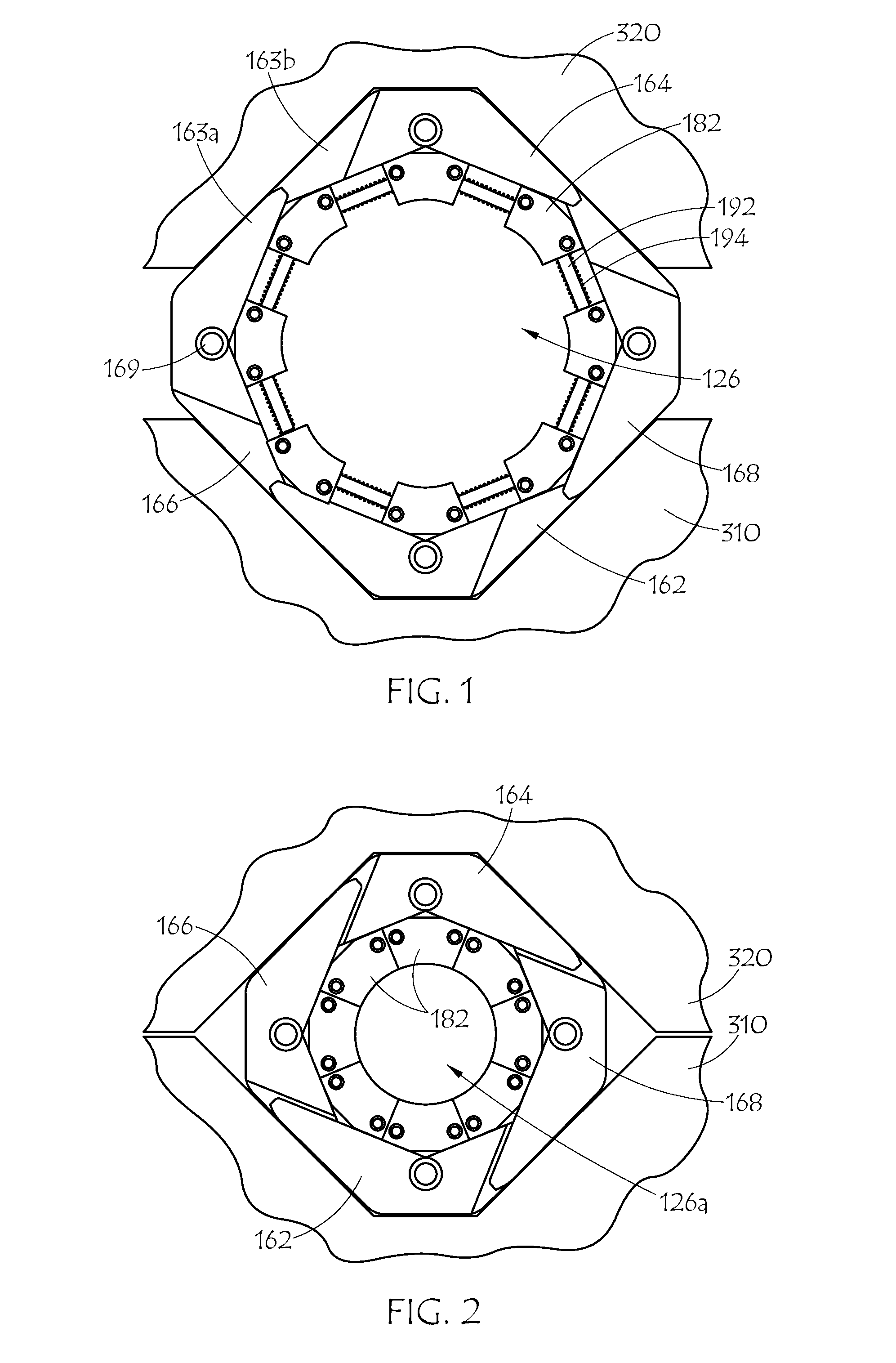
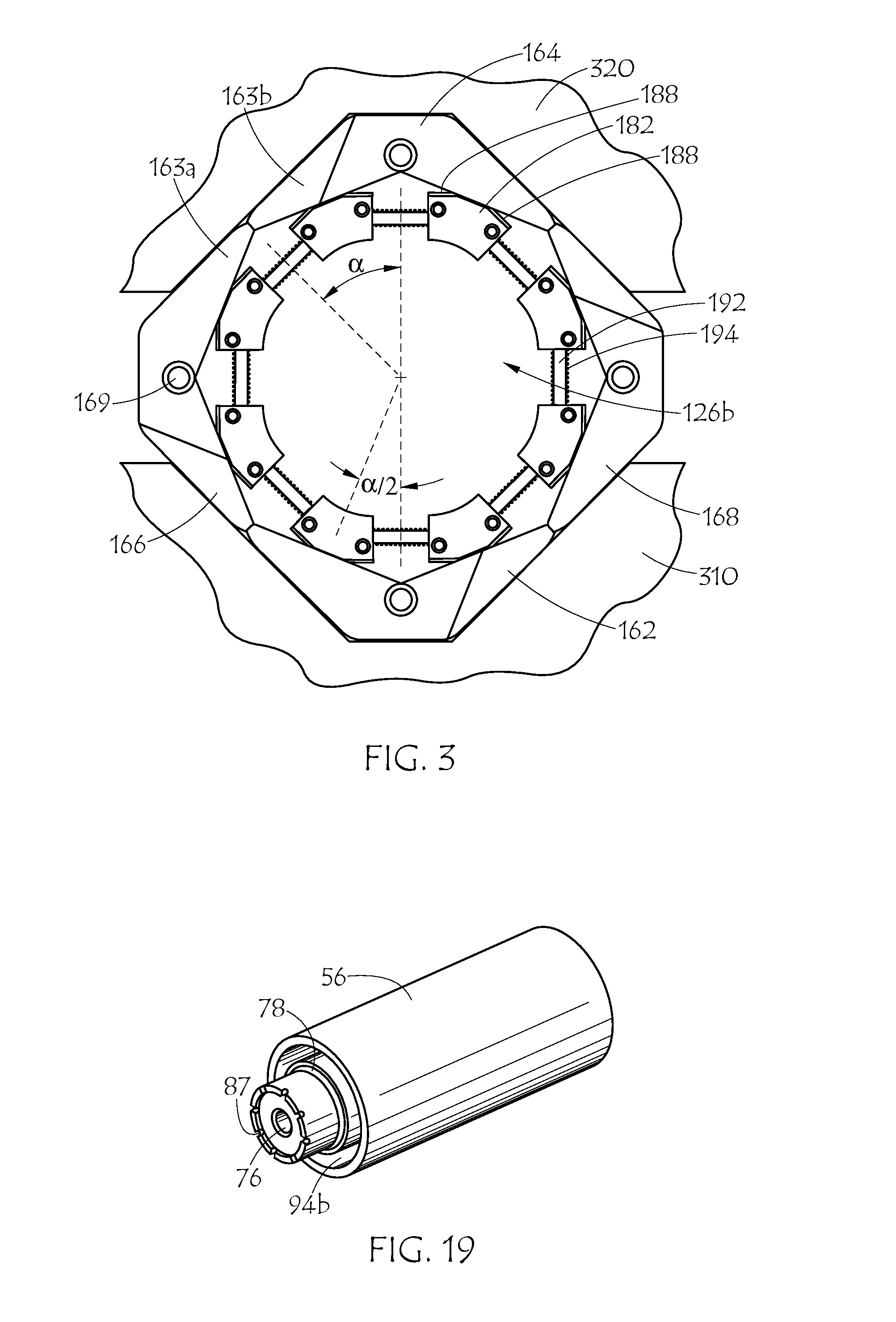
[0057]FIG. 6 illustrates crimper apparatus 300, the present invention in the open position, and FIG. 7 illustrates the same embodiment in the closed or crimping position. The three main features of this embodiment of the invention are: (1) a crimper frame comprising a head and a base which can house the crimper dies; (2) a system of levers and linkages which can be actuated to drive the head and base together in a crimping motion; and (3) a drive mechanism to actuate the linkage. In FIGS. 6 and 7, crimper head 320 is slidably engaged with base 310, defining a polygonal-shaped opening in the resulting frame which is crimp zone 126. As will be seen later, sliders and dies may be mounted in the opening, further defining crimp zone 126. Head and base can slide together because of right frame slide mechanism 314 and left frame slide mechanism 316. The slide mechanism may be based on a channel and slider, or a post, or the like. Indicated in FIG. 6 is a slide mechanism (314 and 316) in wh...

second embodiment

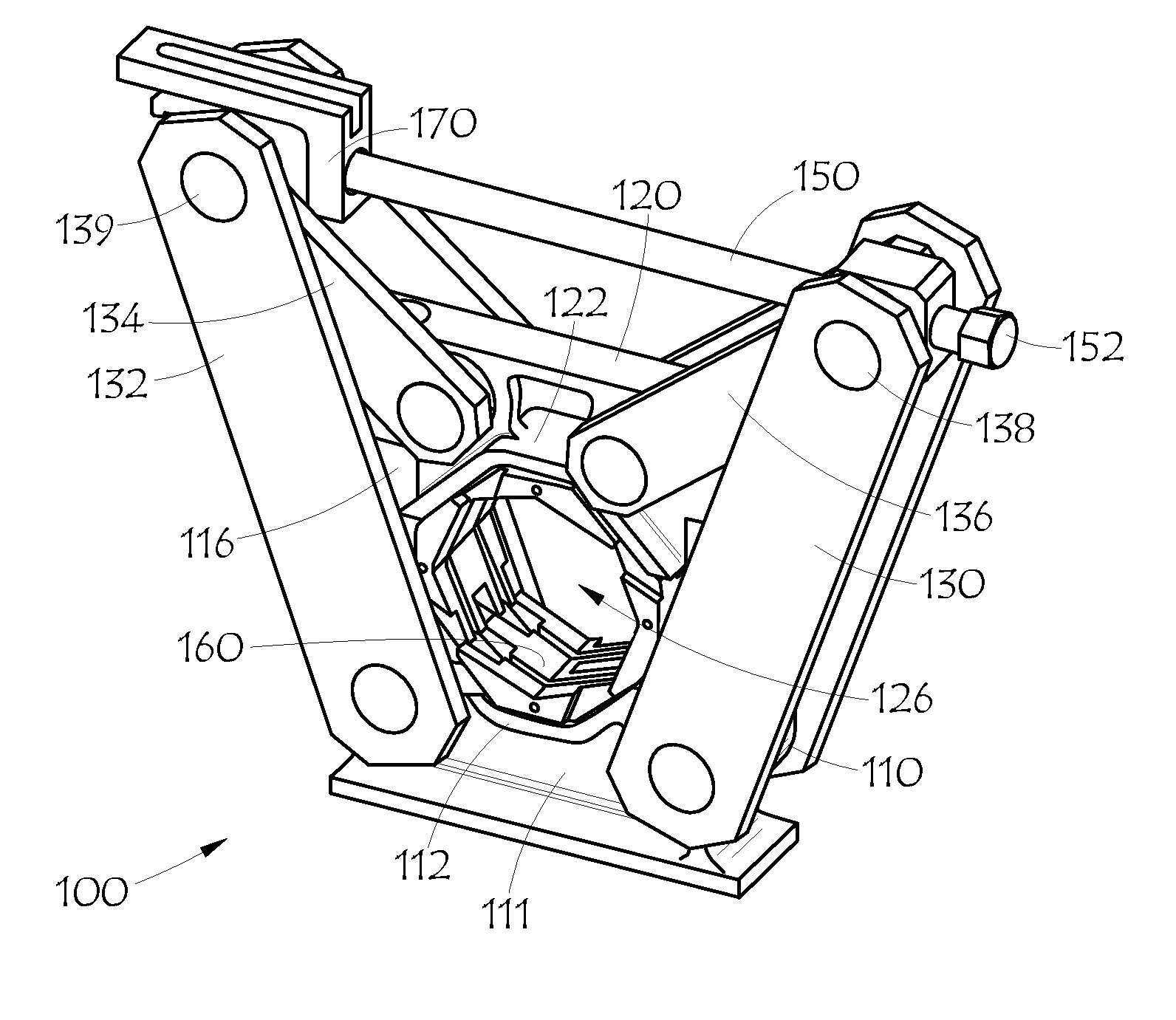
[0076]The driver used to move the left and right elbows towards each other in FIGS. 8 and 9 is drive screw 150, with drive nut 152 which may be a hex head adapted for driving with a socket on a drill / driver or similar device, and with take-up nut 154 on the opposite end of screw 150 from drive nut 152. Drive screw 150 is connected to the left and right elbows by means of left elbow drive connection 156 and right elbow drive connection 158. It should be understood that alternate drive mechanisms could be used as described above in connection with the embodiment of FIGS. 6 and 7.

[0077]Also shown with the second embodiment of FIGS. 8 and 9 is optional adjustable stop mechanism 170. Drive screw 150 and stop mechanism 170 are shown in more detail in FIG. 10. Right elbow drive connection 158 includes pivot housing 157 for right pivot joint 142. On the left end, left elbow drive connection 156 includes take-up pivot housing 159 for left pivot joint 140 and take-up nut 154. Also mounted on ...


PUM


Abstract

A crimper system (300) having a slide frame with a base (310) and a movable head (320) slidably mounted on the slide frame, with a crimp zone (126) opening defined between the base and head includes a dual compound leverage mechanism having two tension arms (332, 330) with lower ends pivotably attached to the base; two compression arms with lower ends pivotably attached to the movable head; and the upper end of each tension arm pivotably attached to the upper end of a corresponding one of the compression arms (334,336) forming two elbow joints defining acute angles between each tension arm and its corresponding compression arm; a screw drive mechanism (350); and a stepped crimp-setting mechanism. Also provided is a tool, system and method for quick, easy removal, installation and storage of multiple-die, crimper die sets. The system includes a set of interconnected dies. The tool engages the connectors for pulling the die set out of a crimper.

Description

BACKGROUND OF THE INVENTION[0001]1. Field of the Invention[0002]This invention relates generally to a crimper for cylindrical couplings, more particularly to a compact, mechanically activated crimper system, and specifically to a screw-operated, dual arm crimping system with a die carrier system of intermeshing, overlapping portions of die carriers, a die system of interconnected dies, a hand tool for changing crimper die sets, and a stop mechanism.[0003]2. Description of the Prior Art[0004]There are many types of crimping machines, i.e., crimpers, for crimping an outer work piece onto an inner work piece. Virtually all devices currently used to crimp hydraulic hose assemblies, i.e., to crimp hydraulic hose end fittings including ferrules, require hydraulic pumps and cylinders. One type of crimper available in the market today utilizes a hydraulic cylinder to ram a set of die segments axially through a generally cone-shaped head as exemplified by U.S. Pat. No. 6,178,802 to Reynolds....

Claims


Application Information

Patent Timeline
Patent Type & Authority Applications(United States)
IPC IPC(8): B21D39/04B25B27/14
CPCB25B27/14B21D39/048B21D39/046B30B7/04Y10T29/5367Y10T483/10B29C65/568
Inventor GILBREATH, DONALD R.
Owner THE GATES CORP
Why Eureka
Try Eureka