
Microscope probe and method for use of same

a microscope and probe technology, applied in the direction of scanning probe techniques, instruments, etc., can solve the problems of inefficient consumption of power, time-consuming and labor-intensive systems,

Active Publication Date: 2014-11-13
GOVERNMENT OF THE UNITED STATES OF AMERICA AS REPRESENTED BY SEC OF COMMERCE THE NAT INST OF STANDARDS & TECH +1
View PDF7 Cites 28 Cited by
  • Summary
  • Abstract
  • Description
  • Claims
  • Application Information

AI Technical Summary

Benefits of technology

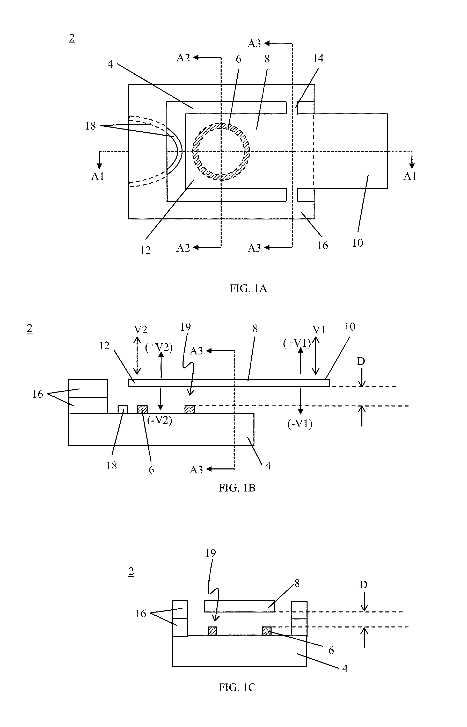
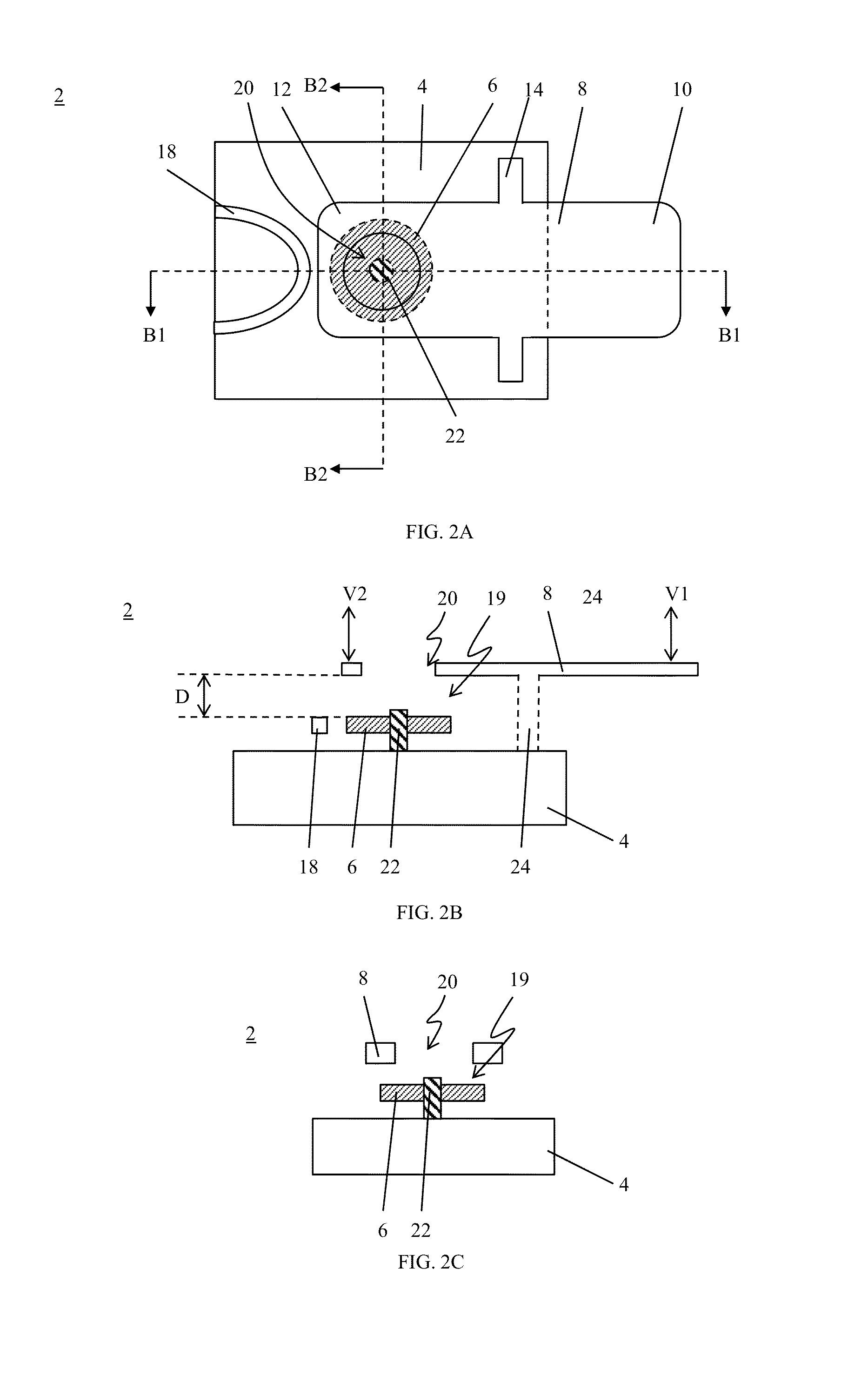
This patent describes a microscope probe that can detect and measure the properties of a sample by using an optical resonator. The microscope probe consists of an optical resonator, a displacement member, and a coupling member that connects the displacement member to the substrate. The displacement member is made up of a first end and a second end. The first end is positioned farthest from the optical resonator and is used to touch the sample. The second end is positioned closest to the optical resonator and is used to change the optical resonance property. When the sample is probed with the first end, the second end communicates the displacement to the substrate, and the substrate changes the optical resonance property in response to this displacement. The microscope probe can be used to acquire information about the sample by measuring the change in optical resonance property caused by the displacement of the second end.

Problems solved by technology

However, engineering of optical systems that include certain photonic materials requires complex and difficult to manufacture components such as modulating and switching devices that need extensive active alignment procedures during fabrication or assembly, resulting in expensive systems that are time-consuming to produce and operate.
Such systems often require conversion between optical signals and electronic signals, which can inefficiently consume power.

Method used


Image

  • Microscope probe and method for use of same
  • Microscope probe and method for use of same
  • Microscope probe and method for use of same

Examples


example 1

[0142]A microscope probe was formed using the process described above. A scanning electron microscope micrograph of the microscope probe is shown in FIG. 38.

example 2

[0143]The microscope probe of Example 2 was subjected to actuation of the actuator to displace the displacement member. The resulting normalized displacement of the displacement member is shown in FIG. 39, with a maximum signal that corresponds to a displacement of about 3 nm.

example 3

[0144]Optical properties of optical resonator.

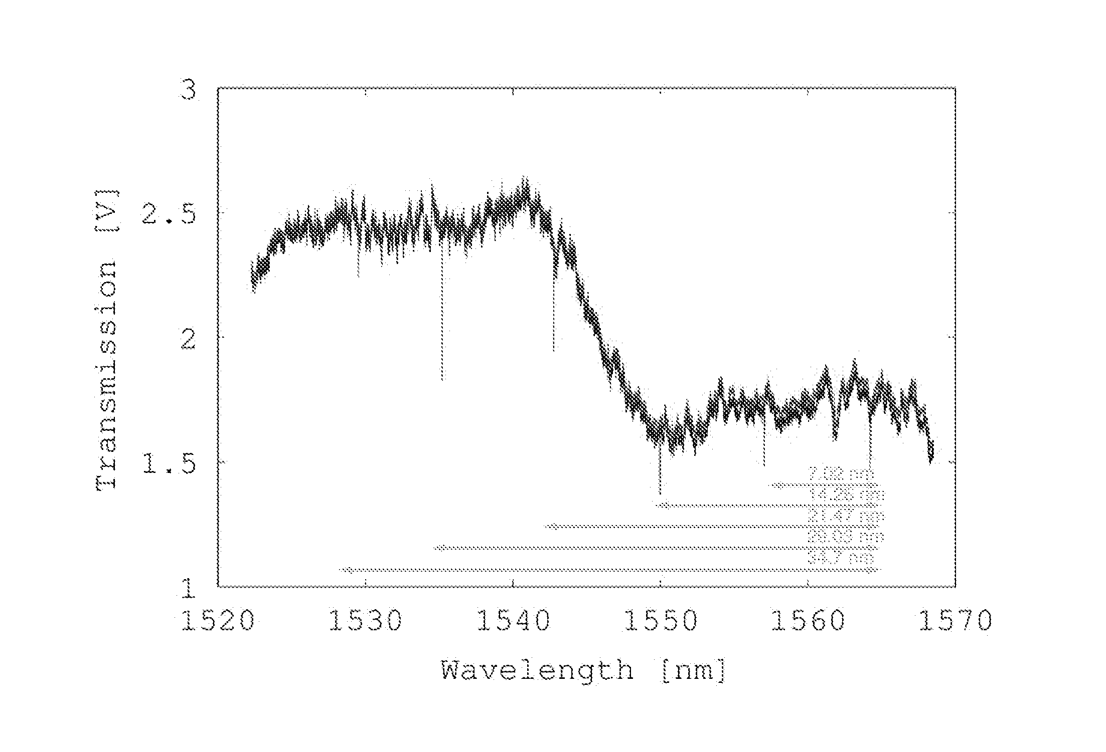
[0145]The optical resonator was subjected to light from a laser and transmitted light from the optical resonator was detector. The spectrum for transmission of transverse electric (TE) mode polarized light was acquired. FIG. 40A shows a graph of transmission versus wavelength for a spectrum of TE mode polarized light acquired as an output signal from the optical resonator of the microscope probe shown in FIG. 38. FIG. 40B shows a graph of relative transmission versus peak number corresponding to the spectrum shown in FIG. 40A. FIG. 40C shows a graph of quality (Q) factor versus peak number corresponding to the spectrum shown in FIG. 40A. FIG. 40D shows a graph of transmission versus wavelength for Peak 2 of the spectrum shown in FIG. 40A.

[0146]The spectrum for transmission of transverse magnetic (TM) mode polarized light was acquired. FIG. 41A shows a graph of transmission versus wavelength for a spectrum of transverse magnetic (TM) mode...


PUM


Abstract

A microscope probe includes a substrate; an optical resonator disposed on the substrate and including an optical resonance property; a displacement member disposed on the substrate and separated from the optical resonator, the displacement member including: a first end disposed distal to the optical resonator; and a second end disposed proximate to the optical resonator; and a coupling member disposed on the substrate and connecting the displacement member to the substrate, wherein the first end is configured to probe a sample and to be displaced in response to a condition of the sample, the displacement member is configured to communicate displacement of the first end to the second end, and the second end is configured to change the optical resonance property in response to displacement of the second end

Description

CROSS REFERENCE TO RELATED APPLICATIONS[0001]This application claims the benefit of U.S. Provisional Patent Application Ser. No. 61 / 826,667 filed May 23, 2013, the disclosure of which is incorporated herein by reference in its entirety.STATEMENT REGARDING FEDERALLY SPONSORED RESEARCH[0002]This invention was made with United States government support from the National Institute of Standards and Technology. The government has certain rights in the invention.BACKGROUND[0003]Photonic materials are a forefront technology in many areas including high speed telecommunications, photometrics, and sensor devices. For example, wavelength division multiplexing techniques are commonly used to independently transmit a plurality of signals over an optical fiber, and independent data streams are carried by optical fields propagating through an optical fiber at different optical carrier wavelengths corresponding to various signal channels. Photonic materials provide high bandwidth and conserved tran...

Claims


Application Information

Patent Timeline
Patent Type & Authority Applications(United States)
IPC IPC(8): G01Q20/02
CPCG01Q20/02
Inventor AKSYUK, VLADIMIRSRINIVASAN, KARTIKMIAO, HOUXUNRANGELOW, IVO W.MICHELS, THOMAS
Owner GOVERNMENT OF THE UNITED STATES OF AMERICA AS REPRESENTED BY SEC OF COMMERCE THE NAT INST OF STANDARDS & TECH
Learn More