Apparatus for parallel operation of pulse-width modulation power converters
a technology of power converters and parallel operation, applied in the direction of power conversion systems, electrical apparatus, control systems, etc., can solve the problems of increasing the voltage limit value, affecting the operation, and affecting the linearity of currents
- Summary
- Abstract
- Description
- Claims
- Application Information
AI Technical Summary
Benefits of technology
Problems solved by technology
Method used
Image
Examples
embodiment 1
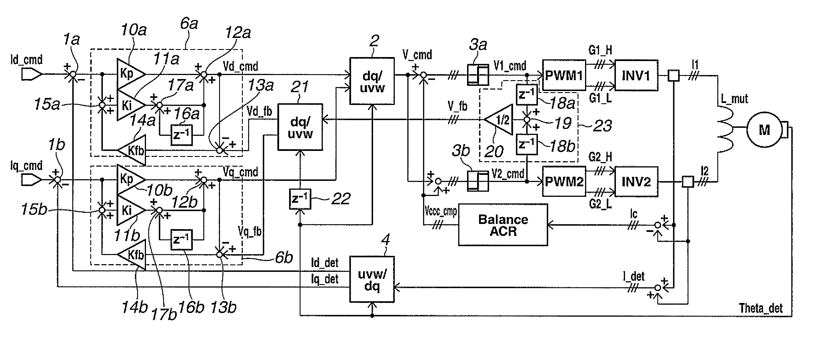
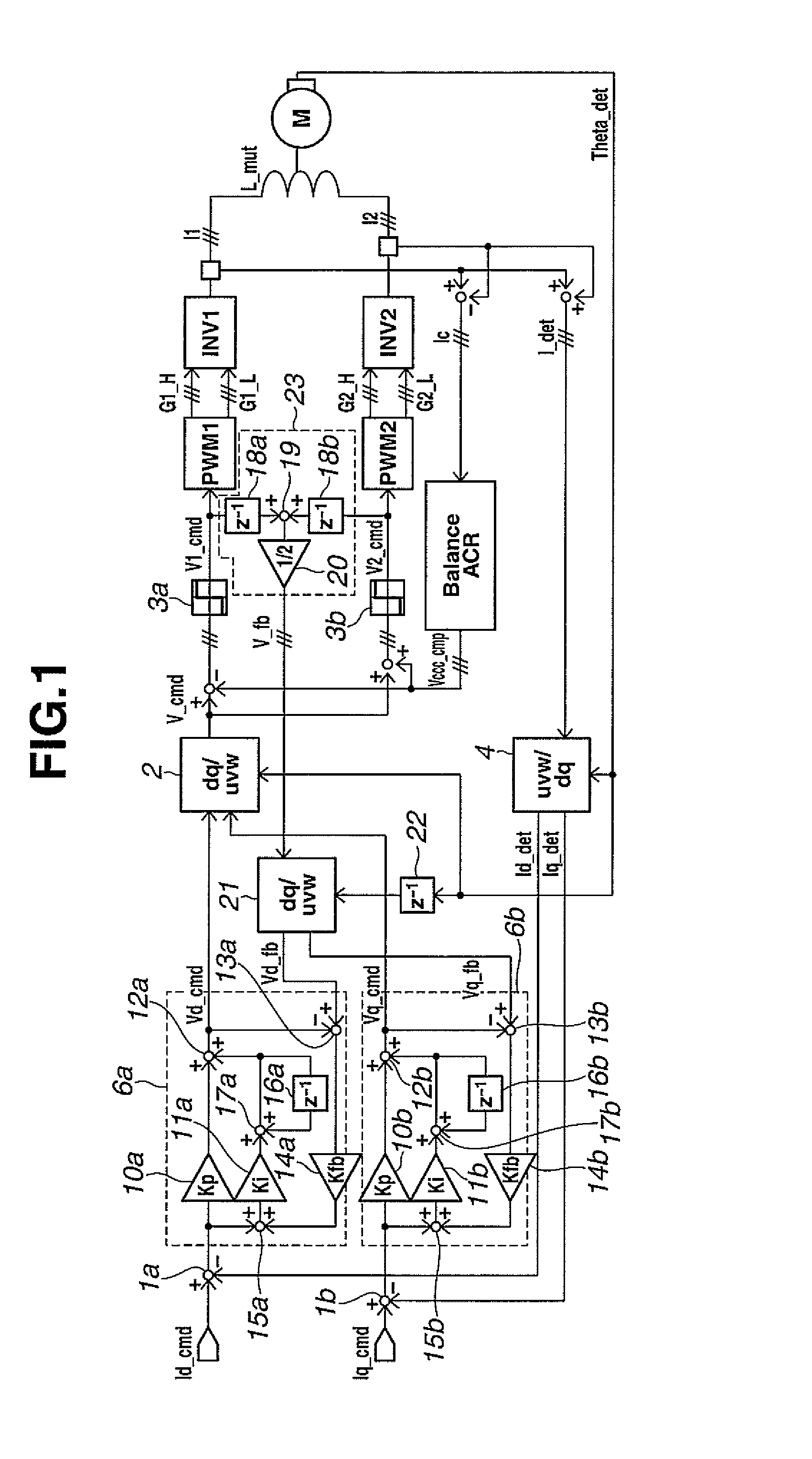
[0035]FIG. 1 is a block diagram showing a PWM power converter parallel running apparatus according to Embodiment 1.
[0036]First, a subtracting section 1a determines a deviation of a d-axis current command value or quantity Id_cmd from a d-axis current detection value or quantity Id_det, and an output current control section 6a performs a PI control. Similarly, a subtracting section 1b determines a deviation of a q-axis current command value or quantity Iq_cmd from a q-axis current detection value or quantity Iq_det, and an output current control section 6b performs a PI control. A dq inverse transformer 2 inversely transforms voltage commands Vd_cmd and Vq_cmd which are outputs of the output current control sections 6a and 6b, into a voltage command V_cmd.
[0037]The dq transformation and the dq inverse transformation are expressed by a following mathematical expression (1). In the mathematical expression (1), θ represents a phase.
[Math.1][Cdq]=23[cosθsinθ-sinθcosθ]·[1-1 / 2-1 / 203 / 2-3 / 2]...
embodiment 2
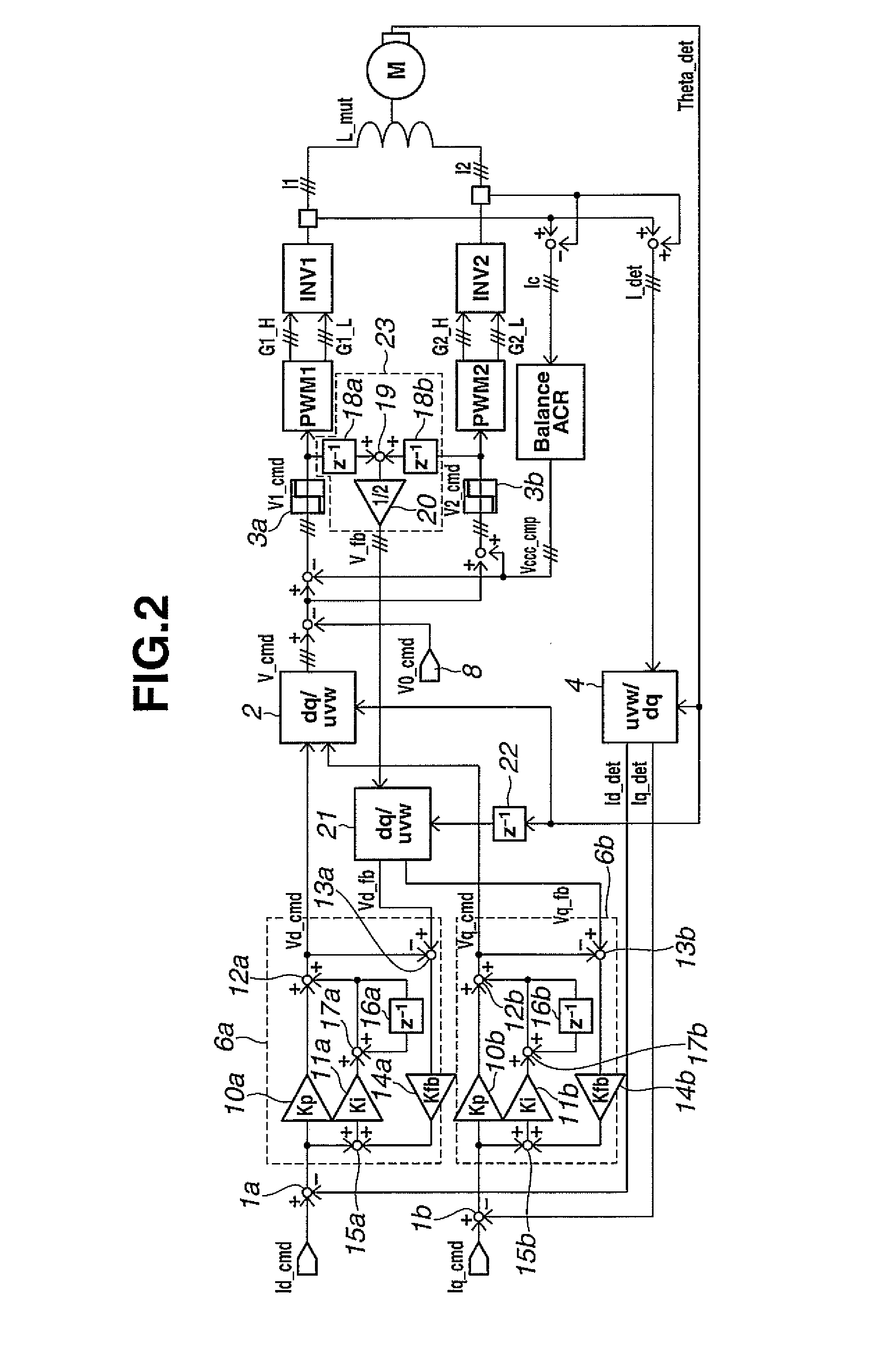
[0053]A PWM power converter parallel running apparatus according to Embodiment 2 is arranged to perform a zero phase modulation to increase a voltage output range unlike the PWM power converter running apparatus according to Embodiment 1.
[0054]FIG. 2 is a block diagram showing the PWM power converter parallel running apparatus according to Embodiment 2. Among various methods proposed as the zero-phase modulation, the following explanation employs, as an example, a method of Patent Document 2. The voltage command V_cmd of each phase is subjected to subtraction of a zero-phase voltage command V0_cmd which is a sine wave having a frequency equaling a triple of a frequency of a fundamental wave. In the example of FIG. 2, the cross current compensation is performed after the subtraction of the zero-phase voltage command V0_cmd from the voltage command V_cmd. The d-axis and q-axis feedback quantities Vd_fb and Vq_fb can be determined in the same operation as in Embodiment 1. The d-axis an...
embodiment 3
[0056]A PWM power converter parallel running apparatus according to Embodiment 3 is arranged to add a dead time compensation to the PWM power converter running apparatus according to Embodiment 2.
[0057]For explanation of the dead time compensation, FIG. 4 shows a time chart of the dead time compensation. FIG. 4 shows the time chart of inverter INV1 only. First, an error time measurement value or quantity Vce_DLY1 is a value determined by measurement between the gate command Gate1 and an inverter phase voltage detection value or quantity Vce1 at the on time and the off time. In order to use the error time measurement quantity Vce_DLY1 for the dead time compensation, a dead time compensating section 9 obtains a dead time compensating voltage Vdtc_cmp1 [p.u.] which is a quantity obtained by converting the error time measurement quantity Vce_DLY1 to the form in the unit (voltage) identical to the unit of the voltage command quantity V_cmd [p.u.]. This dead time compensating voltage Vdtc...
PUM
 Abstract
Description
Claims
Application Information
 - R&D
- Intellectual Property
- Life Sciences
- Materials
- Tech Scout
- Unparalleled Data Quality
- Higher Quality Content
- 60% Fewer Hallucinations
Browse by: Latest US Patents, China's latest patents, Technical Efficacy Thesaurus, Application Domain, Technology Topic, Popular Technical Reports.
© 2025 PatSnap. All rights reserved.Legal|Privacy policy|Modern Slavery Act Transparency Statement|Sitemap|About US| Contact US: help@patsnap.com


