
Mold comprising a cavity for molding a device for closure in a groove

a molding device and groove technology, applied in the field of tire manufacturing, can solve the problems of changing the flexibility reducing the height of the closure device, and unsatisfactory for people situated inside the vehicle and/or outside the vehicle, and achieves the effect of improving the demolding of the closure device and simple and practical manner

Active Publication Date: 2014-11-06
MICHELIN & CO CIE GEN DES ESTAB MICHELIN
View PDF0 Cites 4 Cited by
  • Summary
  • Abstract
  • Description
  • Claims
  • Application Information

AI Technical Summary

Benefits of technology

The invention makes it easy to create molding cavities in a mold. This helps to make small closure devices that can flex when driving over a wet road surface.

Problems solved by technology

This resonance tube amplifies the running noise of the tire, and this may be unpleasant for people situated inside the vehicle and / or outside this vehicle.
It has been found that the flexibility of these devices changes over time.
Thus, with tire wear, the height of these closure devices decreases, thus causing their rigidity to increase.
These closure devices may therefore ultimately prevent water from circulating properly in the groove.
Thus, with tread wear, the region of attachment of each closure device to the associated wall of the groove decreases.
However, in order to mold these closure devices into a groove, it is necessary to make slots in the lateral faces of a bar of a mold, it not being appropriate for these slots to open onto the upper surface of this bar.
Now, creating these slots with the required degree of precision is accompanied by a great many difficulties.

Method used


Image

  • Mold comprising a cavity for molding a device for closure in a groove
  • Mold comprising a cavity for molding a device for closure in a groove
  • Mold comprising a cavity for molding a device for closure in a groove

Examples


Embodiment Construction

[0054]In the description which follows, elements which are substantially identical or similar will be denoted by identical references.

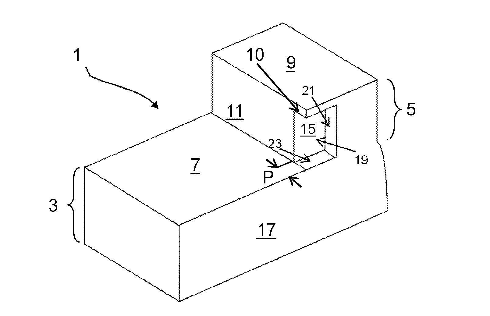
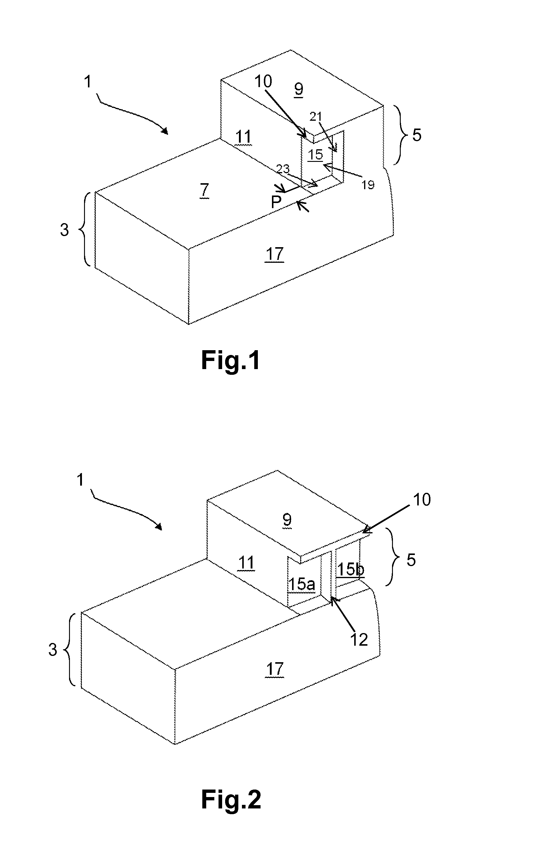
[0055]FIG. 1 schematically depicts a perspective view of a molding element 1 of a mold according to a first embodiment of the invention.

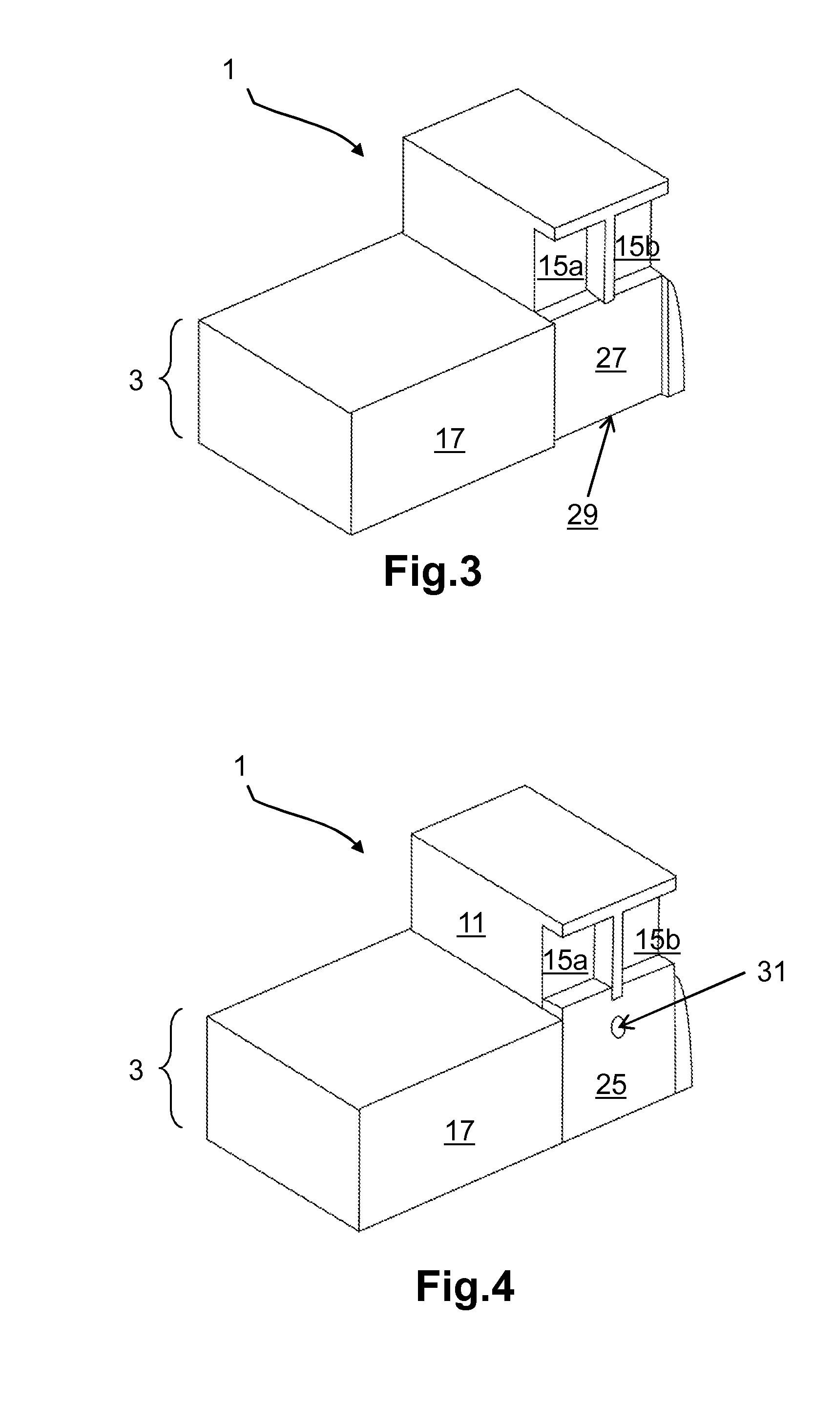
[0056]The molding element 1 comprises a base 3 and a bar 5 projecting from the said base 3. The base 3 and the bar 5 are in this instance formed as one from the same substance and made of a material of the aluminium type.

[0057]More particularly, the base 3 comprises a molding surface 7 intended to mold part of the tread surface of a tire. The bar 5 for its part comprises an upper face 9 intended to mold the bottom of a groove and two lateral faces 11, just one of which is depicted here. These lateral faces 11 project from the molding surface 7 of the base 3 and extend along the length of the bar.

[0058]To make the invention easier to understand, the bar 5 has been depicted here as being in the overall shape of a rectan...


PUM

PropertyMeasurementUnit
widthaaaaaaaaaa
widthaaaaaaaaaa
widthaaaaaaaaaa

Abstract

A molding element for a mold for vulcanizing a tread of a tire, comprising a base able to mold part of the tread surface of the tread and a bar able to mold a groove in the tread, the bar comprising two lateral faces extending along its length and projecting from the base and an upper face connecting the lateral faces. The molding element comprises a contact edge formed by the base and the bar, intended to come into contact with another molding element to form all or part of the vulcanizing mold, and further comprising at least one recess in the bar, which opens onto one of the lateral faces and onto the contact edge, but does not open onto the upper face of the bar.

Description

[0001]This application is a 371 National Stage Application of PCT / EP2012 / 073435, filed Nov. 23, 2012, which claims the benefit of FR1160778, filed Nov. 25, 2011, the entire contents of each of which are incorporated herein by reference for all purposes.BACKGROUND[0002]1. Field[0003]The present field relates to the field of the manufacture of a mold for a tire comprising a plurality of cavities which are able to mold closure devices in one or more groove(s) of this tire. More particularly, the field relates to the manufacture of a mold formed from a plurality of molding elements.[0004]2. Description of Related Art[0005]Document WO 2010146180 discloses a vulcanizing mold for a tire comprising a plurality of molding elements. Each moldingelement is delimited by two edges in contact with two other adjacent moldingelements so that once the molding elements are in contact with one another, all of these molding elements together allow all or part of the tread of the tire to be molded.[0006...

Claims


Application Information

Patent Timeline
Patent Type & Authority Applications(United States)
IPC IPC(8): B29D30/06
CPCB29D30/0606B29D2030/0612B29D2030/061
Inventor VILLENEUVE, BERNARDROTY, GAELGREVERIE, LUDOVIC
Owner MICHELIN & CO CIE GEN DES ESTAB MICHELIN
Learn More