
Vegetation cutting device

Inactive Publication Date: 2014-11-06
BLACK & DECKER INC
View PDF8 Cites 9 Cited by
  • Summary
  • Abstract
  • Description
  • Claims
  • Application Information

AI Technical Summary

Benefits of technology

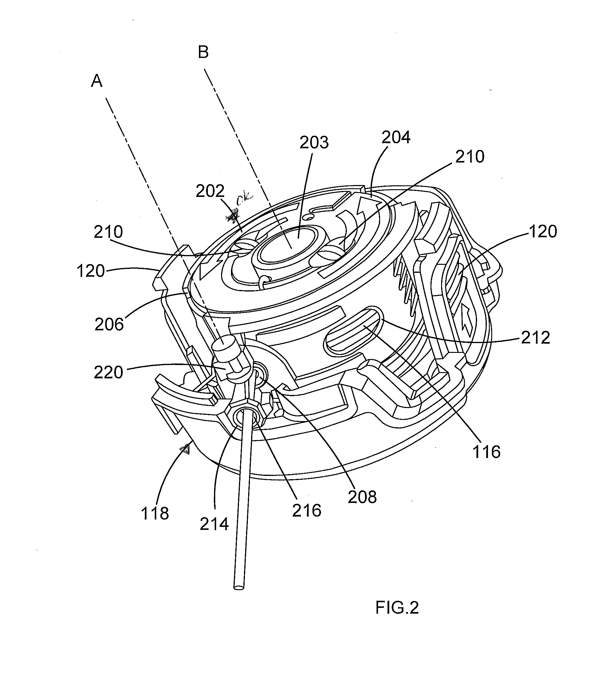
This patent describes a cutting device for vegetation that includes a gripping arm that constantly holds the cutting line on the spool when not in use. The gripping arm moves from a gripping position to a release position due to the rotation of the spool. This design prevents the cutting line from unwinding and makes it easier to install and thread the line onto the device. The gripping arm grips the cutting line over a plurality of locations and does not deform or damage the line. The device also includes a spool sleeve with a gripping arm that automatically returns to the gripping position when not in use. The spool sleeve can guide the cutting line in a predetermined direction, making installation easier and improving operation of the feeding mechanism. The spool sleeve also includes a counterweight to balance the gripping arm when the cutting head is rotating at a speed for cutting vegetation.

Problems solved by technology

During use of a string trimmer the cutting line can break if the line impacts a hard surface or object.
This means if the cutting line breaks, the user must disassemble the cutting head and manually replace the cutting line.
This can be difficult and cumbersome for the user particularly if the cutting head is heavily soiled.
A problem with U.S. Pat. No. 5,339,526 is the clamp portions are always gripping the cutting line.
In addition, the clamp portions are a weak and inefficient way to clamp the line.
This will disrupt the feeding mechanism and feed out too much cutting line.
In addition by pinching the cutting line at one point the cutting line is more susceptible to being damaged and will break more easily.
If the cutting line breaks, the counterweight is unbalanced against the centrifugal forces of the shortened free end of the cutting line and the counterweight will move and actuate the feeding mechanism.
A problem with this automatic feed mechanism is that the spool accessory requires the user to thread the cutting line through the openings in the cutting head.
Threading the cutting line into the cutting head can be difficult for the user.

Method used


Image

  • Vegetation cutting device
  • Vegetation cutting device
  • Vegetation cutting device

Examples


Embodiment Construction

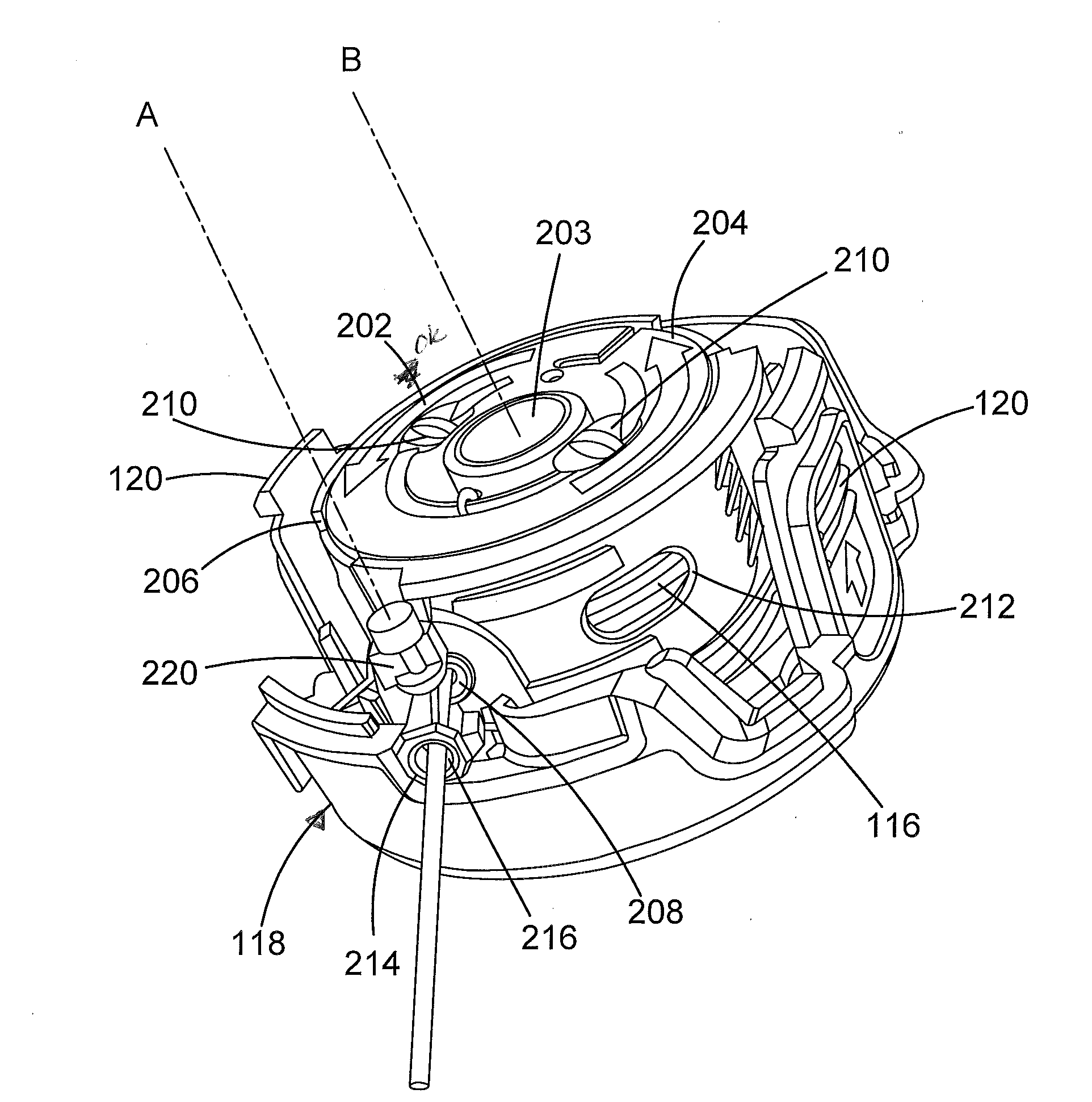
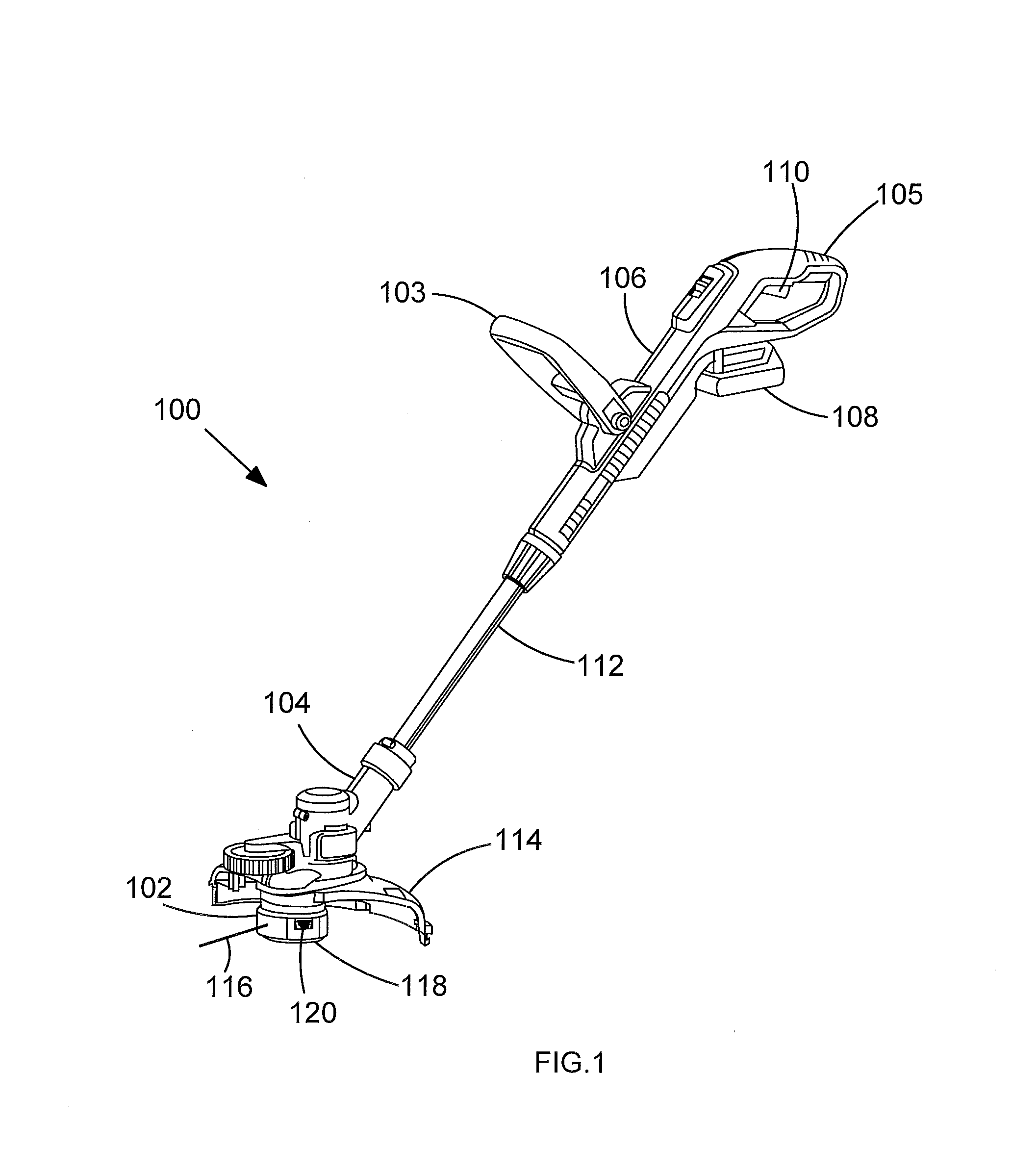
[0035]FIG. 1 shows a perspective view of a vegetation cutting device or string trimmer 100. Typically the vegetation cutting device 100 is a string trimmer and the term string trimmer will be used hereinafter, but the vegetation cutting device can alternatively be other devices suitable for cutting vegetation. For example the vegetation cutting device can be a lawn mower comprising a cutting line.

[0036]In some embodiments the string trimmer 100 comprises a cutting head housing 104 for housing a motor (not shown) and other components. The cutting head housing 104 can comprise two clam shell portions which are fixed together to enclose the motor and other components. A cutting head 102 is rotatably mounted to the cutting head housing 104 and the cutting head 102 connected to the motor via a rotatable drive shaft (not shown). The cutting head comprises a cutting element 116 configured to cut vegetation when the cutting head 102 is rotated. The cutting element 116 in some embodiments is...


PUM


Abstract

A spool accessory for a rotatable cutting head of a vegetation cutting device comprises: a spool configured to receive a cutting line wound thereon; and a spool sleeve mounted to the spool, the sleeve comprising a gripping arm moveable between a gripping position wherein the gripping arm grips the cutting line wound on the spool and a release position wherein the gripping arm does not engage the cutting line wound on the spool, wherein the gripping arm is configured to move from the gripping position to the release position when the cutting head rotates.

Description

[0001]This application claims priority to European Patent Application No. 13 166 510.1 filed May 3, 2013. The entire contents of that application are expressly incorporated herein by reference.FIELD OF THE INVENTION[0002]The present invention relates to a vegetation cutting device. In particular the present invention relates to a spool accessory for a cutting line for a vegetation cutting device.BACKGROUND OF THE INVENTION[0003]Vegetation cutting devices such as string trimmers are known power operated tools for cutting grass and other foliage and vegetation. Typically string trimmers are powered by petrol or electricity and an engine or motor drives a cutting head. The cutting head can comprise one or more rotating blades, in which case the trimmer is generally known as a brush cutter or one or more rotating cutting lines, in which case it is known as a string trimmer.[0004]A vegetation cutting device such as a string trimmer comprises a rotating cutting head with a cutting line mo...

Claims


Application Information

Patent Timeline
IPC IPC(8): A01D34/416
CPCA01D34/4166A01D34/4162
Inventor BONE, GRAHAM
Owner BLACK & DECKER INC
Learn More