
RF Connector

a technology of connectors and sockets, applied in the direction of coupling device connections, electrical apparatus, two-part coupling devices, etc., can solve the problems of high locking force, large connector housings, complex mechanical design, and high cost, and achieve simple and robust mechanical design, high return loss, and easy manufacturing at low cost

Active Publication Date: 2014-10-30
SPINNER
View PDF3 Cites 22 Cited by
  • Summary
  • Abstract
  • Description
  • Claims
  • Application Information

AI Technical Summary

Benefits of technology

The invention provides a RF coaxial plug-and-socket connector that can connect at high frequencies with low intermodulation and high return loss. The connectors have a simple and robust mechanical design and can be easily manufactured at low cost in high volumes. The plug and socket connectors have accurate positioning mechanisms for alignment in the direction of their center axis when mated. The connectors have precision centering means and a conical shape to ensure a low tolerance for lateral movement and an even current distribution, leading to high return loss and low passive intermodulation. The socket connector has a circular protrusion at its inner side to facilitate capacitive coupling and improve high frequency performance. Overall, the invention provides a reliable and efficient connection for high-speed RF applications.

Problems solved by technology

This necessitates a comparatively massive connector housing and high locking forces.
The drawback is that the outer conductor current path varies with mechanical tolerances and the relative position between the plug part and the socket part.
The disadvantages of this design are its complexity and the associated costs.
Furthermore, centering is not provided, as the plug connector has spring elements at the outer conductor to compensate for centering deviations.
This does not result in a well-defined axial positioning.

Method used


Image

  • RF Connector
  • RF Connector
  • RF Connector

Examples


Embodiment Construction

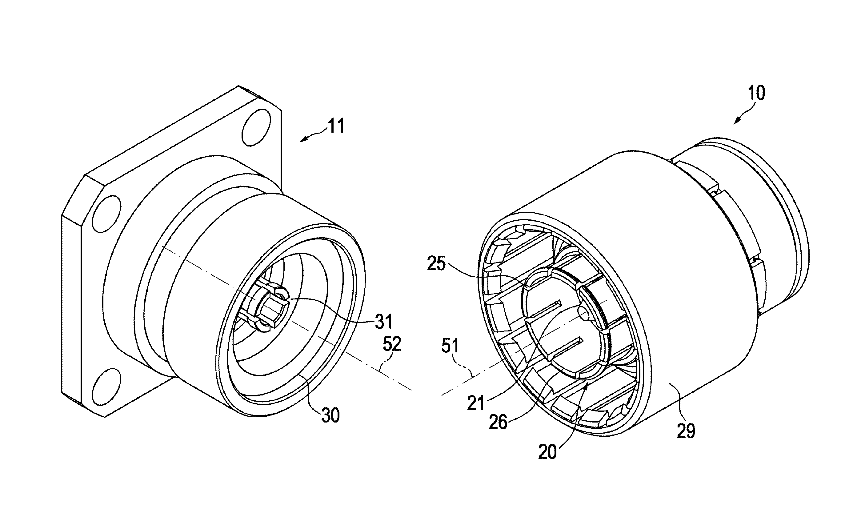
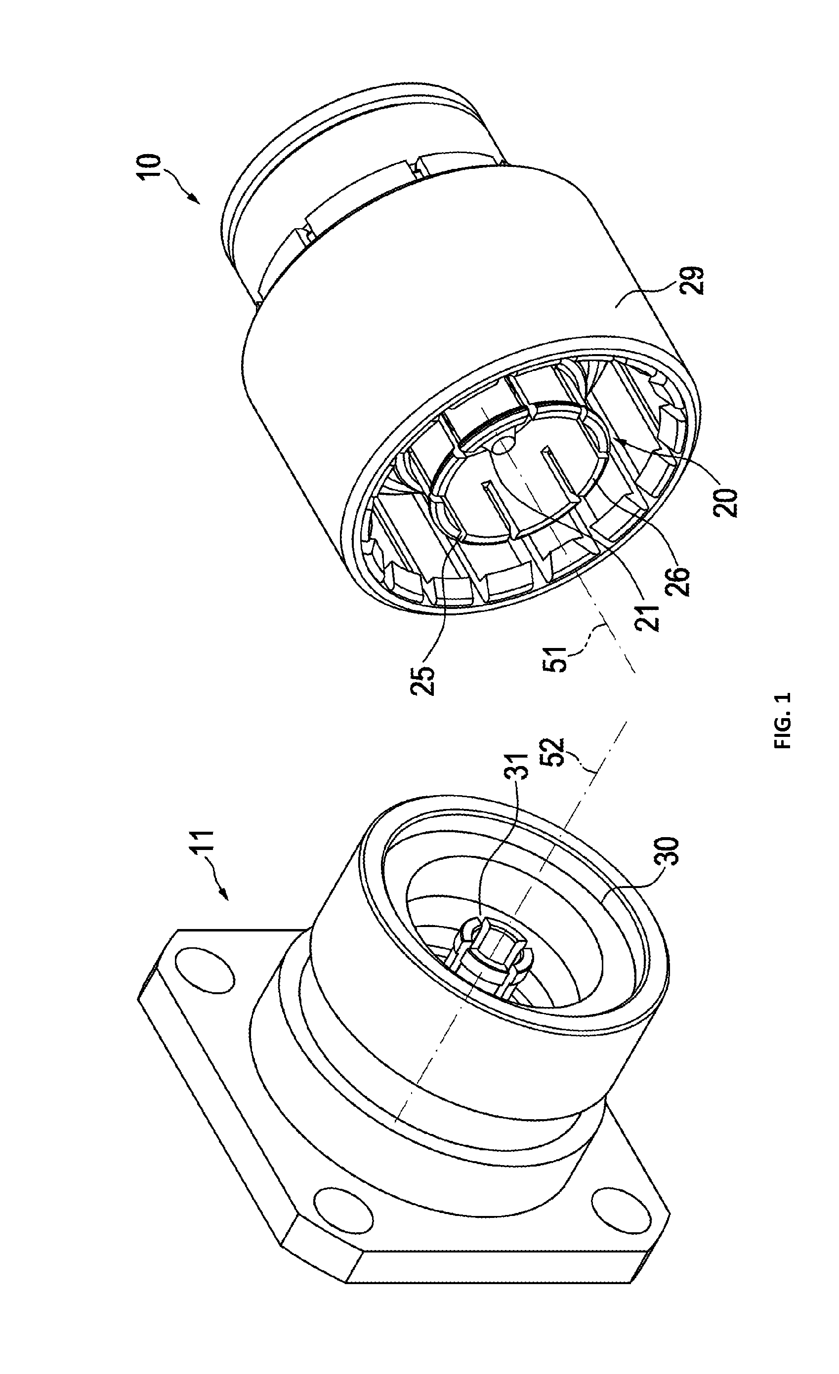
[0032]In FIG. 1, a coaxial socket connector 11 and a coaxial plug connector 10 are shown. The coaxial socket connector 11 includes at least one center conductor 31 and one outer conductor 30. A center axis 52 of the socket connector is defined by the center of center conductor 31.

[0033]The complementary coaxial plug connector 10 includes at least one center conductor 21 and one outer conductor 20. A center axis 51 of the plug connector is defined by the center of center conductor 21. When mated with the coaxial socket connector 11, the center axis 51, 52 coincide. The outer conductor includes a plurality of slits 25 with lands in between, forming a plurality of spring loaded contact elements 26 at its socket connector-facing end. At least one locking means 29 is provided for locking or fastening the plug connector 10 to the socket connector 11. The locking means may be of screw type or bayonet type.

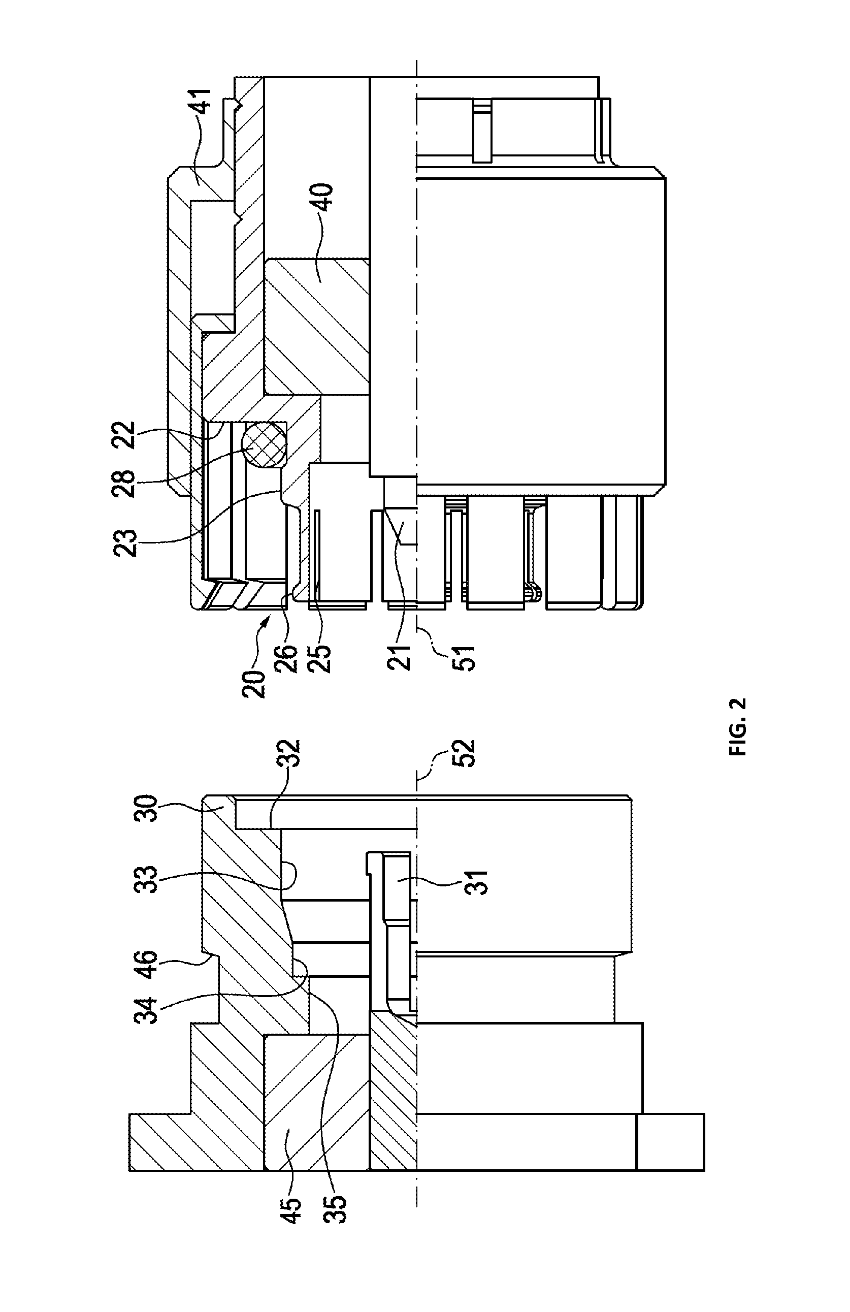
[0034]FIG. 2 shows sectional views of the socket connector 11 and the plug connector ...


PUM


Abstract

A coaxial connector system comprises a coaxial plug connector and socket connector. The coaxial connectors have a center conductor defining a center axis of the connector and an outer conductor coaxial to the center conductor. The plug connector's outer conductor has a cylindrical shape with slits forming a plurality of spring loaded contact elements, while the socket connector's outer conductor is a cylindrical shape forming a contact surface. Furthermore, the connectors have a mechanical contact surface at a right angle to their center axis and distant from the spring loaded contact elements and the contact surface. Cylindrically precision centering means are provided at the connectors, which fit into each other and precisely align the center axis of the connectors resulting in reduced passive intermodulation. This design allows for further reducing contact gaps between the outer and inner conductors to further improve return loss at high frequencies.

Description

PRIORITY CLAIM[0001]This application is a continuation of pending International Application No. PCT / EP2013 / 050165 filed on 7 Jan. 2013, which designates the United States and claims priority from European Application No. 12150763.6 filed on Jan. 11, 2012, both of which are incorporated by reference in their entireties.BACKGROUND OF THE INVENTION[0002]1. Field of the Invention[0003]The invention relates to a coaxial plug-and-socket connector for radio frequencies (RF), comprising a socket part and a plug part and further comprising a precision centering means of the socket part and the plug part.[0004]2. Description of Relevant Art[0005]RF connectors as disclosed in the U.S. Pat. No. 4,929,188, having a frontal contact of the outer conductors, require a significant minimum pressure between the plug part and the socket part to obtain a low intermodulation connection. This necessitates a comparatively massive connector housing and high locking forces.[0006]The US Patent Application Pub...

Claims


Application Information

Patent Timeline
IPC IPC(8): H01R24/40H01R13/631
CPCH01R13/6315H01R24/40H01R2103/00H01R13/629H01R24/44
Inventor BINDER, THOMASDOVRANIC, ZLATKO
Owner SPINNER
Learn More