
Stereoscopic 3-D Presentation for Air Traffic Control Digital Radar Displays

a technology of digital radar and air traffic control, applied in the field of visualizing air traffic, can solve the problems of ripple effect, high aircraft density, and difficulty in presenting air traffic controllers with difficult decisions

Active Publication Date: 2014-10-16
THE UNITED STATES OF AMERICA AS REPRESETNED BY THE SEC OF THE AIR FORCE
View PDF9 Cites 15 Cited by
  • Summary
  • Abstract
  • Description
  • Claims
  • Application Information

AI Technical Summary

Benefits of technology

The invention provides a method and apparatus for displaying air traffic data to an air traffic controller. The method involves receiving data about multiple aircraft, determining the spacing between each aircraft, and generating left and right eye images of the aircraft based on the determined spacing. The left and right eye images are then displayed simultaneously on a display, creating a three-dimensional separation of the aircraft. The apparatus includes a memory, processor, and display, and the program code is designed to receive air traffic data, determine the spacing between the aircraft, and generate the left and right eye images for display. The technical effect of the invention is to provide a more realistic and efficient way for air traffic controllers to visualize and analyze airspace.

Problems solved by technology

The multiple criteria of safety and expeditiousness often conflict, presenting the air traffic controller with difficult decisions.
Specifically, while the air traffic controller may wish to maintain a large separation between aircraft to enable safe flight, the need to move large numbers of aircraft through a constrained air space requires a high aircraft density.
Further, while the air traffic controller may wish to redirect aircraft which have a potential conflict, these redirects cause the aircraft to maneuver, requiring more fuel and disrupting prior planning, potentially causing a ripple effect as the redirected aircraft becomes more likely to enter the path of another aircraft.
Because controllers have an incredibly large responsibility while on duty and make countless split-second decisions on a daily basis, the ATC profession is consistently regarded around the world as one of the most mentally challenging careers, and can be notoriously stressful depending on many variables including equipment, configurations, weather, traffic volume, human factors, etc.
Despite years of effort and billions of dollars spent on computer software designed to assist air traffic control, success has been largely limited to improving the tools at the disposal of the controllers, such as computer-enhanced digital radar.
These calculations involve labor intensive mental processes which are fatiguing and task the situational awareness of the controllers.
Additionally, on-screen data clutter reduces situational awareness and task vigilance and also adds to workload rather than reducing it.

Method used


Image

  • Stereoscopic 3-D Presentation for Air Traffic Control Digital Radar Displays
  • Stereoscopic 3-D Presentation for Air Traffic Control Digital Radar Displays
  • Stereoscopic 3-D Presentation for Air Traffic Control Digital Radar Displays

Examples


Embodiment Construction

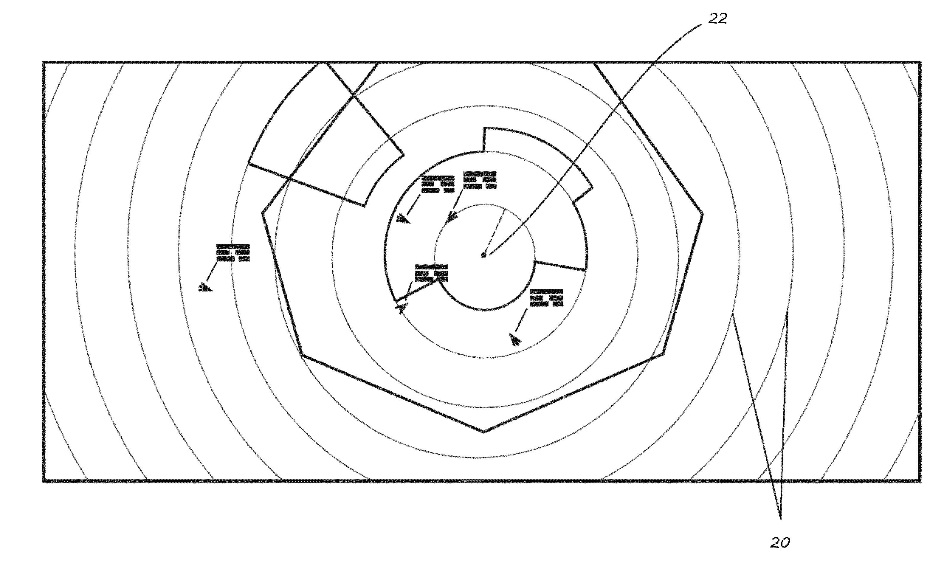
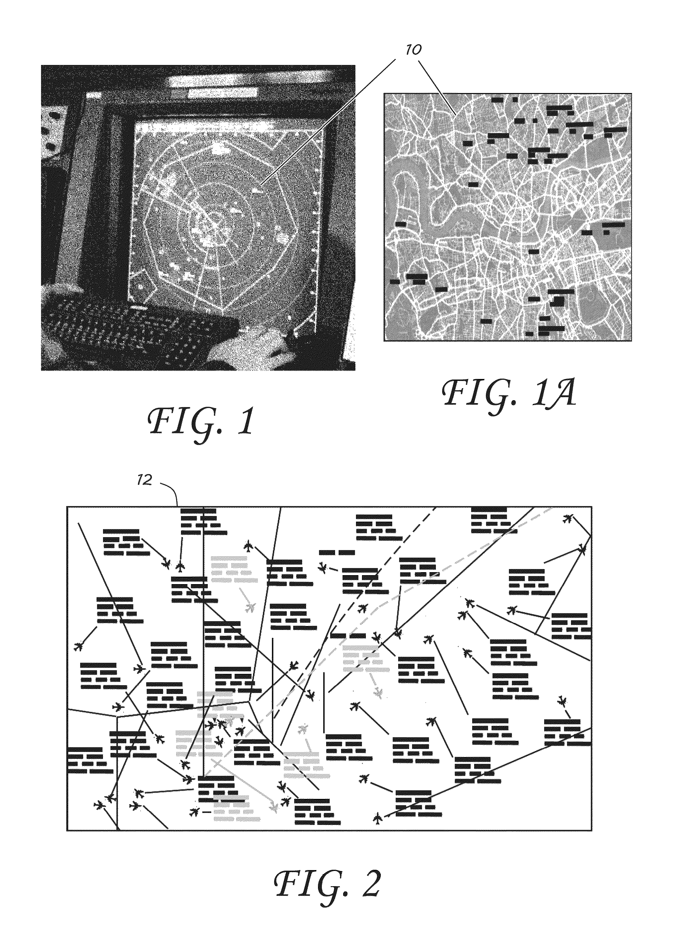
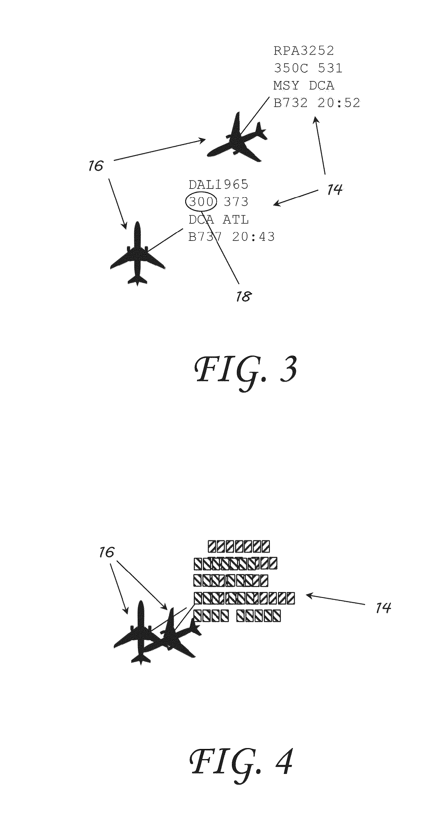
[0034]As air traffic becomes increasingly more congested, managing the safety of air traffic by air traffic controllers is becoming increasingly more challenging as illustrated in the exemplary display 12 in FIG. 2. Aircraft identification, type, altitude, and speed are conventionally displayed in an information block, referred to as a “data tag” associated with each aircraft symbol. Exemplary information blocks 14 and aircraft symbols 16 may be seen in a simplified display in FIG. 3. Contemporary displays provide only a two dimensional view of the aircraft 16 with a vertical indication 3-digit altitude code to represent altitude. For example, reference number 18 shows an altitude code of 300, which indicates that the aircraft is at 30,000 ft altitude. Thus, spatial vertical position and orientation of the aircraft in the 3-D volume of airspace is left to controller's mental image creation, which, with the volume of aircraft in a given sector is mentally tasking and contributes to f...


PUM


Abstract

An apparatus and method of presenting air traffic data to an air traffic controller are provided. Air traffic data including a two dimensional spatial location and altitude for a plurality of aircraft is received. A disparity value is determined based on the altitude for each aircraft of the plurality of aircraft. Left and right eye images are generated of the plurality of aircraft where at least one of the left and right eye images is based on the determined disparity value. The left and right eye images are simultaneously displayed to the air traffic controller on a display. The simultaneously displayed images provide an apparent three-dimensional separation of each of the aircraft of the plurality of aircraft on the display.

Description

CROSS-REFERENCE TO RELATED APPLICATIONS[0001]This application claims the benefit of and priority to U.S. Provisional Application Ser. No. 61 / 768,573, entitled “Stereoscopic 3-D Presentation for Air Traffic Control Digital Radar Displays,” filed on Feb. 25, 2013, the entirety of which is incorporated by reference herein.RIGHTS OF THE GOVERNMENT[0002]The invention described herein may be manufactured and used by or for the Government of the United States for all governmental purposes without the payment of any royalty.BACKGROUND OF THE INVENTION[0003]1. Field of the Invention[0004]The present invention generally relates to Air Traffic Control and, more particularly, visualizing air traffic.[0005]2. Description of the Related Art[0006]Air traffic control (ATC) is a service provided by ground-based controllers who direct aircraft on the ground and through controlled airspace. The primary purpose of ATC systems worldwide is to separate aircraft to prevent collisions (referred to as separ...

Claims


Application Information

Patent Timeline
Patent Type & Authority Applications(United States)
IPC IPC(8): G06T15/00G06T7/00H04N13/30G01S13/933
CPCG06T7/0051G06T15/005H04N2013/0081H04N13/30H04N13/302H04N13/337G01S13/933
Inventor RUSSI, JASON G.LANGHALS, BRENT T.MILLER, MICHAEL E.HEFT, ERIC L.
Owner THE UNITED STATES OF AMERICA AS REPRESETNED BY THE SEC OF THE AIR FORCE
Learn More