
Paper punch with adjustable punch seats

Inactive Publication Date: 2014-10-16
PAO SHEN ENTERPRISES
View PDF9 Cites 2 Cited by
  • Summary
  • Abstract
  • Description
  • Claims
  • Application Information

AI Technical Summary

Benefits of technology

This patent relates to a punch press machine with a control member that can adjust the distance between the punch holes. The control member has an operation board and an eccentric seat that is connected to the punch seat. The eccentric seat has two faces, and when the seat is moved, a gap is created between the seat and the punch seat, allowing the punch seat to move. The user can easily adjust the punch hole distance by operating the operation board. The machine also allows for easy replacement or addition of punch seats, providing flexibility in adjustment.

Problems solved by technology

A conventional paper punch has fixed punch seats so that the punch heads are located at fixed positions and the punch holes punched through the sheets are not able to be adjusted.
This fixed feature cannot satisfy the practical needs when organizing documents.
However, the bolt 73 is too small and has to be threadedly connected to the threaded hole of the punch seat 70 so as to position the slide board 61, so that the bolt 73 can easily drop or lost during assembling.
When punching holes through the sheets, the punch seat 70 is not firmly installed and may shift or shake.

Method used


Image

  • Paper punch with adjustable punch seats
  • Paper punch with adjustable punch seats
  • Paper punch with adjustable punch seats

Examples


Embodiment Construction

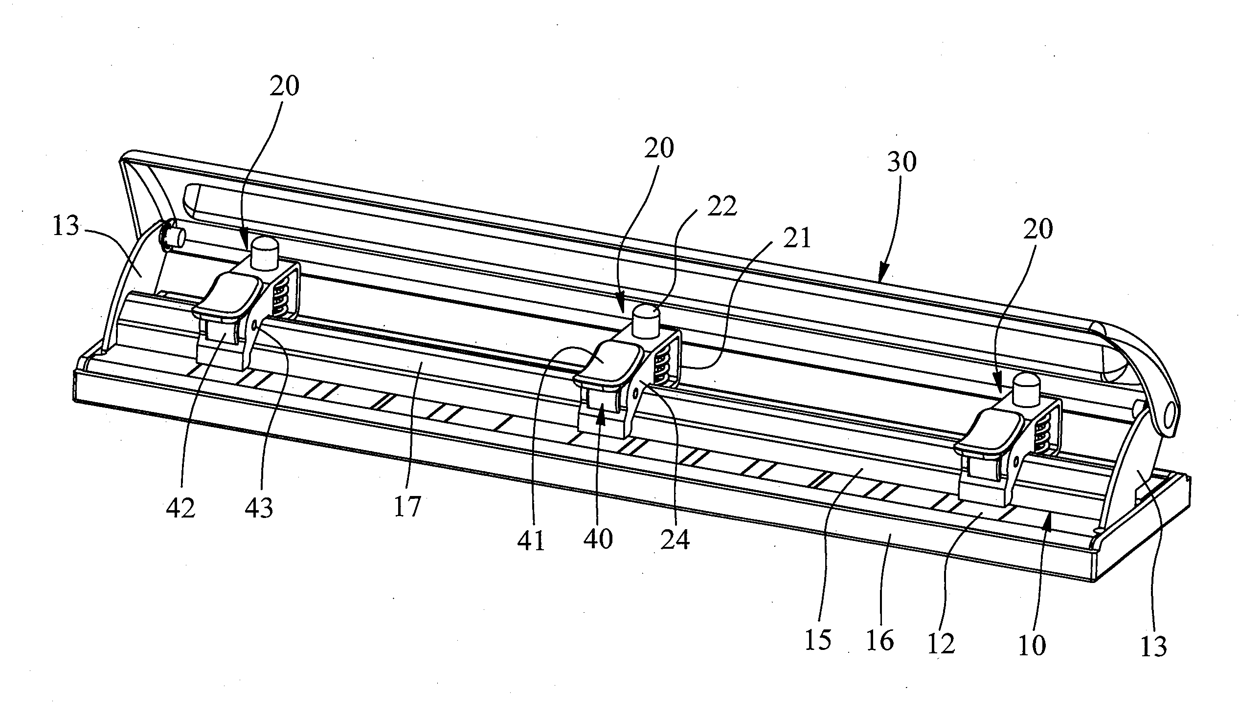
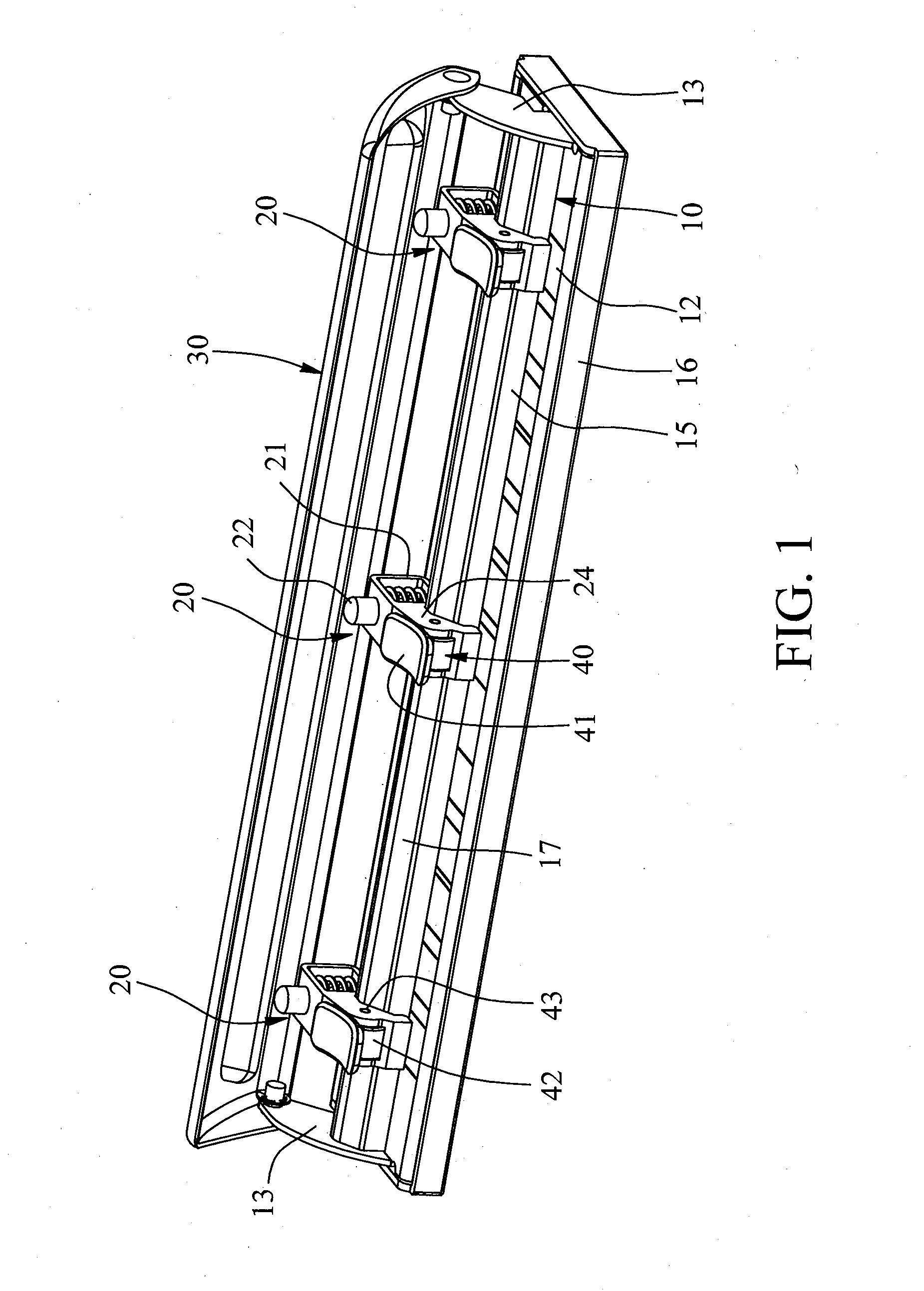
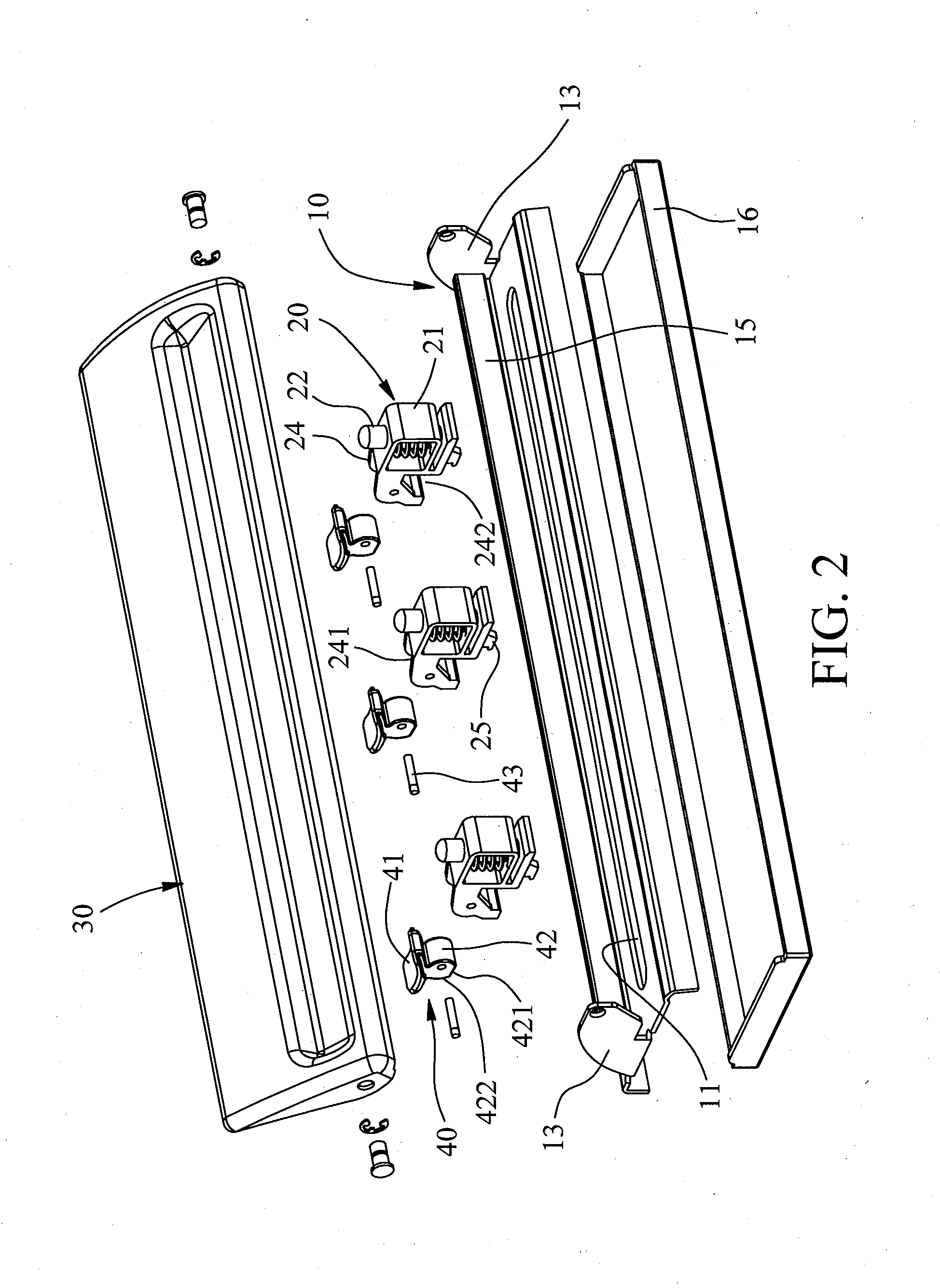
[0025]Referring to FIGS. 1 and 2, the paper punch of the present invention comprises a base 10, multiple punch seats 20 and a press board 30.

[0026]The base 10 has an elongate hole 11 defined in the front end thereof so that debris drop from the hole 11, and an index area 12 is formed on the rear end of the base 10. The base 10 has two support arms 13 extending upward from two ends thereof, and a slide board 15 is connected between the two support arms 13. A connection box 16 is installed to the underside of the base 10 to collect the debris from the hole 11. The press board 30 is pivotably connected to two respective top ends of the two support arms 13.

[0027]The multiple punch seats 20 are connected to the slide board 15 and located corresponding to the hole 11. Each punch seat 20 has a frame 21 and a punch head 22 which is installed to the frame 21 upright and able to return to its initial position by a spring. The punch head 22 punches holes through paper sheets. The frame 21 has ...


PUM


Abstract

A paper punch includes a base and a slide board is connected to the base. Multiple punch seats are located on the slide board and above the hole of the base. Each punch seat has a control member and a connection arm connected to the slide board. The control member is pivotably connected to the connection arm. The control member has an eccentric seat and an operation board. The eccentric seat is a cam and eccentrically connected to the connection arm. A first face is defined in the eccentric seat and located in opposite to the operation board. A second face is located adjacent to the first face. When switching the first face to the second face, the punch seat is movable along the slide board so as to obtain a desired distance between the punch seats.

Description

FIELD OF THE INVENTION[0001]The present invention relates to a paper punch, and more particularly, to a paper punch with movable punch seats so as to adjust the distance between punch holes.BACKGROUND OF THE INVENTION[0002]A conventional paper punch has fixed punch seats so that the punch heads are located at fixed positions and the punch holes punched through the sheets are not able to be adjusted. This fixed feature cannot satisfy the practical needs when organizing documents. As shown in FIG. 7, a punch holes adjustable device is developed and generally comprises multiple punch seats on an elongate base. The paper punch has a base 60 and an L-shaped slide board 61 is connected to the base 60. Distance indexes 62 are marked on the outside of the top of the curved portion of the slide board 61. The slide board 61 further has a slot 63. The punch seats 70 each have a frame 72 with a punch head 71 located therein. The frame 72 has a threaded hole which faces the slide board 61 so tha...

Claims


Application Information

Patent Timeline
IPC IPC(8): B26F1/36
CPCB26F1/36Y10T83/8828
Inventor HUANG, TSUNG-WEN
Owner PAO SHEN ENTERPRISES
Learn More