
Image forming apparatus, image forming method, and medium

a technology of image forming and forming method, which is applied in the direction of electrographic process apparatus, instruments, optics, etc., can solve the problems of inability to stably measure glossiness, inability to cause the glossiness measuring apparatus and the measurement surface to come into contact with each other, and inability to measure glossiness stably, etc., to achieve high gloss accuracy and control, the effect of uniform gloss

Inactive Publication Date: 2014-10-09
CANON KK
View PDF5 Cites 2 Cited by
  • Summary
  • Abstract
  • Description
  • Claims
  • Application Information

AI Technical Summary

Benefits of technology

The present invention aims to provide an image forming apparatus that can accurately measure the glossiness of an image. This allows for better control of gloss uniformity, resulting in a more stable and accurate image.

Problems solved by technology

However, the above-mentioned prior arts have problems described below.
In the case where glossiness is measured during the period of sheet conveyance within the image forming apparatus using the method described in Japanese Patent Laid-Open No. 2004-70010, it is not possible to cause the glossiness measuring apparatus and the measurement surface to come into contact with each other.
Because of this, the glossiness measuring method (60-degree glossiness) described in Japanese Patent Laid-Open No. 2004-70010 has such a problem that the magnitude of deviation between the center of the light reflected from the measurement surface in the regular reflection direction and the center of the light receiving unit is great, and therefore, it is not possible to stably measure glossiness.
However, in the case where the incidence angle θ is set to a deep angle, there is such a problem that the measurement accuracy of glossiness is reduced due to diffused reflection light that is absorbed and scattered inside the image and then emitted from the image surface.
In particular, in the case of a coloring material with which the difference in diffused reflection light between the non-image part and the image part is large, a change in the quantity of diffused light caused by gradation affects the measurement value of glossiness and there has been such a problem that it is not possible to measure glossiness with high accuracy.

Method used


Image

  • Image forming apparatus, image forming method, and medium
  • Image forming apparatus, image forming method, and medium
  • Image forming apparatus, image forming method, and medium

Examples


first embodiment

[0038]First, image processing by an image forming apparatus using the electrophotographic recording system according to the present embodiment is explained.

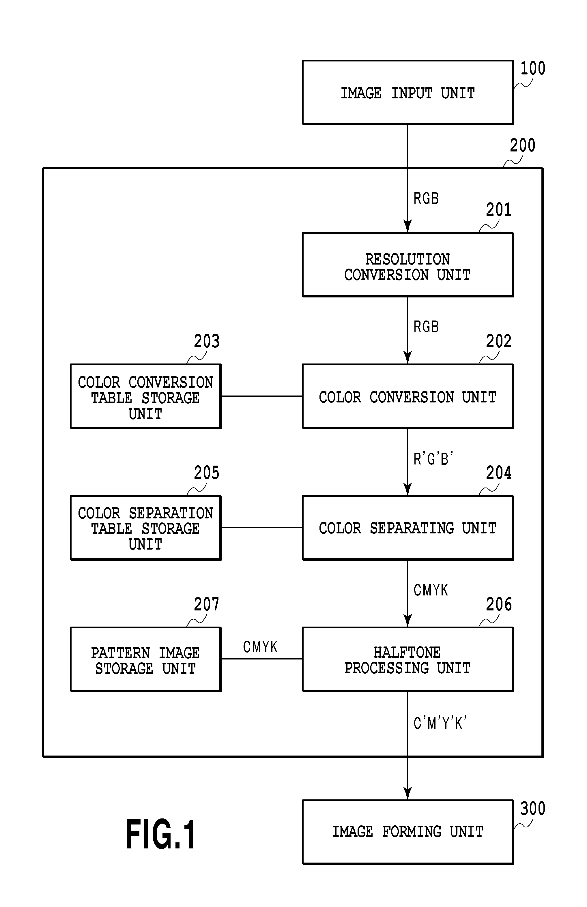
[0039]FIG. 1 is a block diagram for explaining a configuration of an image forming system according to the present embodiment. As shown in FIG. 1, the image forming system includes an image input unit 100, an image processing unit 200, and an image forming unit 300.

[0040]The image input unit 100 is implemented by, for example, application software that operates on a host computer, and transmits image data to the image processing unit 200.

[0041]The image processing unit 200 includes a resolution conversion unit 201, a color conversion unit 202, a color conversion table storage unit 203, a color separation unit 204, a color separation table storage unit 205, a halftone processing unit 206, and a pattern image storage unit 207.

[0042]The image processing unit 200 converts input image data received from the image input unit 100 into p...

second embodiment

[0087]In the first embodiment, the case is explained where the glossiness at the same gradation is equal regardless of the color of toner. Because the glossiness at the same gradation is equal regardless of the color of toner, it is possible to apply the glossiness measured with an image of toner, which is part of toner of a plurality of colors, as the glossiness of another toner image.

[0088]However, for example, in the case where the amount of attached toner for each gradation or the fusing point of toner differs depending on the color of toner, there is a possibility that the coarseness of the surface roughness changes, and therefore, the glossiness differs even for the same gradation.

[0089]Because of this, in order to embody the present invention more effectively, an image forming apparatus for measuring glossiness of toner for each color is explained below.

[0090]FIG. 14 is a diagram showing a configuration of the image forming apparatus according to the present embodiment. The c...

third embodiment

[0101]In the second embodiment, the method for measuring the intensity of regular reflection light having a wavelength with which the change in diffused reflection light between the non-image part and the image part is sufficiently small compared to the change in specular reflection light between the non-image part and the image part by changing the light source of the light emitting unit is explained.

[0102]In the present embodiment, glossiness is determined using the intensity of regular reflection light having a wavelength with which the difference in diffused reflection light between the non-image part and the image part is sufficiently small compared to the difference in specular reflection light between the non-image part and the image part by separating regular reflection light reflected from the measurement surface according to wavelength and by measuring the intensity of regular reflection light. The configuration of the image forming apparatus in the present embodiment is t...


PUM


Abstract

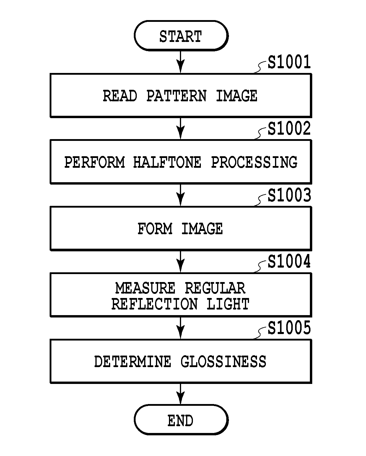
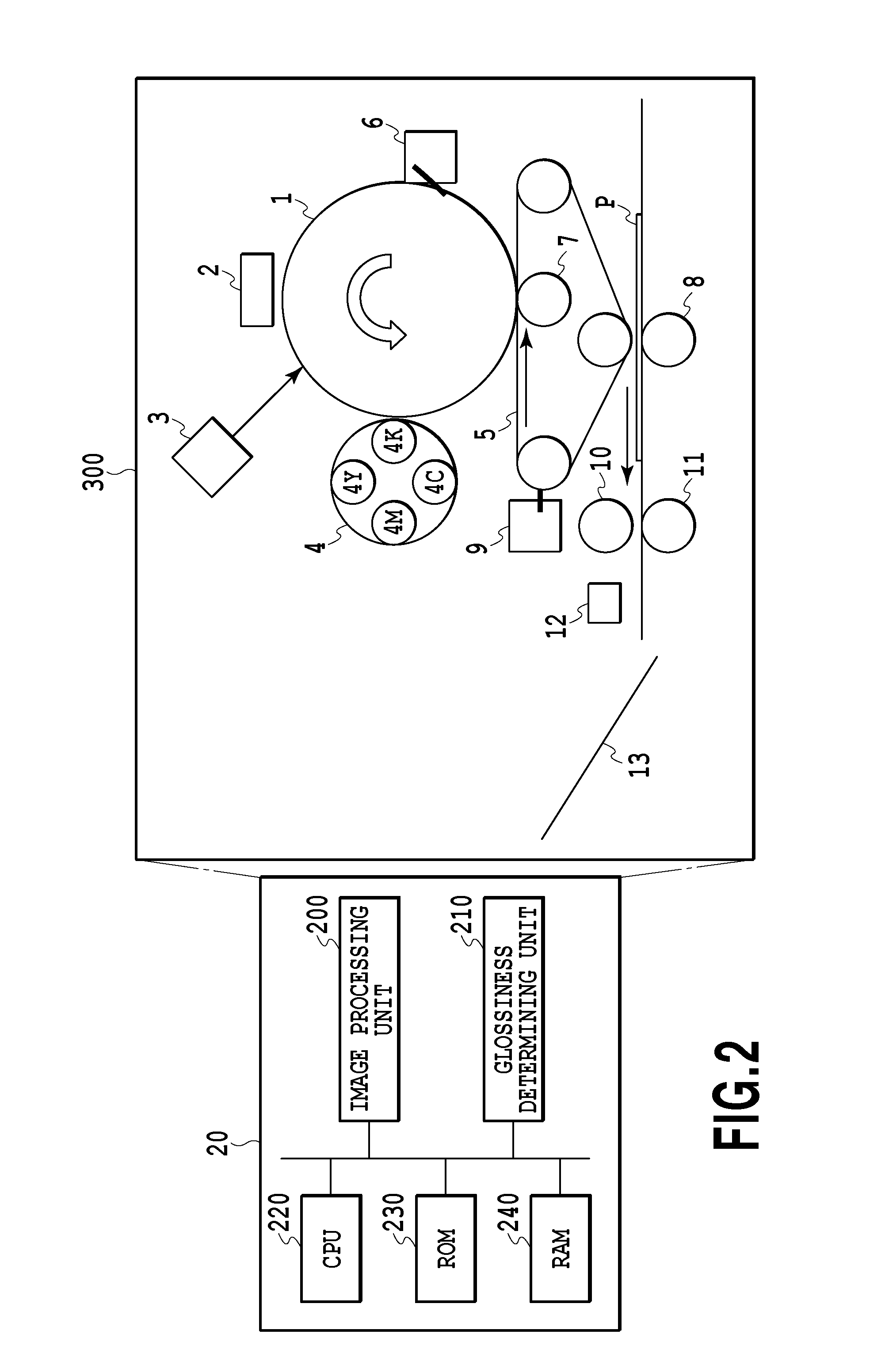
There is provided an image forming apparatus for forming an image using coloring materials of a plurality of colors. The image forming apparatus includes a regular reflection light measuring unit configured to measure regular reflection light of an image formed by a coloring material of a color with which a difference in diffused reflection light between a non-image part and an image part on a recording medium is relatively small compared to a difference in specular reflection light of the coloring materials of the plurality of colors at an angle by which a quantity of received light to be measured by a light receiving unit becomes stable in a case where distance between the light receiving unit and a measurement surface varies and a glossiness determining unit configured to determine glossiness based on the intensity of regular reflection light measured by the regular reflection light measuring unit.

Description

BACKGROUND OF THE INVENTION[0001]1. Field of the Invention[0002]The present invention relates to an image forming apparatus, an image forming method, and a medium.[0003]2. Description of the Related Art[0004]In an image forming apparatus, such as a copy machine and a printer, an image is formed by attaching a coloring material onto a sheet and a plurality of gradations is represented by changing the area of attached coloring material (area coverage modulation). Because of this, in the case where the glossiness of a non-image part (part to which no coloring material is attached) and the glossiness of an image part to which a coloring material is attached are different, there occurs a difference in gloss depending on the gradation even within the same image, and therefore, the gloss uniformity is marred.[0005]In general, in order to increase the gloss uniformity, the glossiness of the non-image part and the glossiness of the image part are grasped in advance for each type of sheet and...

Claims


Application Information

Patent Timeline
Patent Type & Authority Applications(United States)
IPC IPC(8): G03G15/00
CPCG03G15/5025G03G15/5062
Inventor OTANI, RYOSUKE
Owner CANON KK
Learn More