Low-, medium-, or high-voltage switchgear

a switchgear and low-, medium- or high-voltage technology, applied in the field of switchgear, can solve problems such as reducing voltage strength

Inactive Publication Date: 2014-10-09
ABB (SCHWEIZ) AG
View PDF2 Cites 2 Cited by
  • Summary
  • Abstract
  • Description
  • Claims
  • Application Information

AI Technical Summary

Benefits of technology

The patent describes a switchgear that can handle high-voltage equipment and has a device to limit the sudden surge of electricity when the switch is turned on. This helps to prevent damage to the equipment being switched.

Problems solved by technology

During a number of opening operations, the contacts will be damaged more and more, and material will be transferred between the contacts and microtips are developed which can decrease voltage strength especially in a gap between the contacts.

Method used


Image

  • Low-, medium-, or high-voltage switchgear
  • Low-, medium-, or high-voltage switchgear

Examples


Embodiment Construction

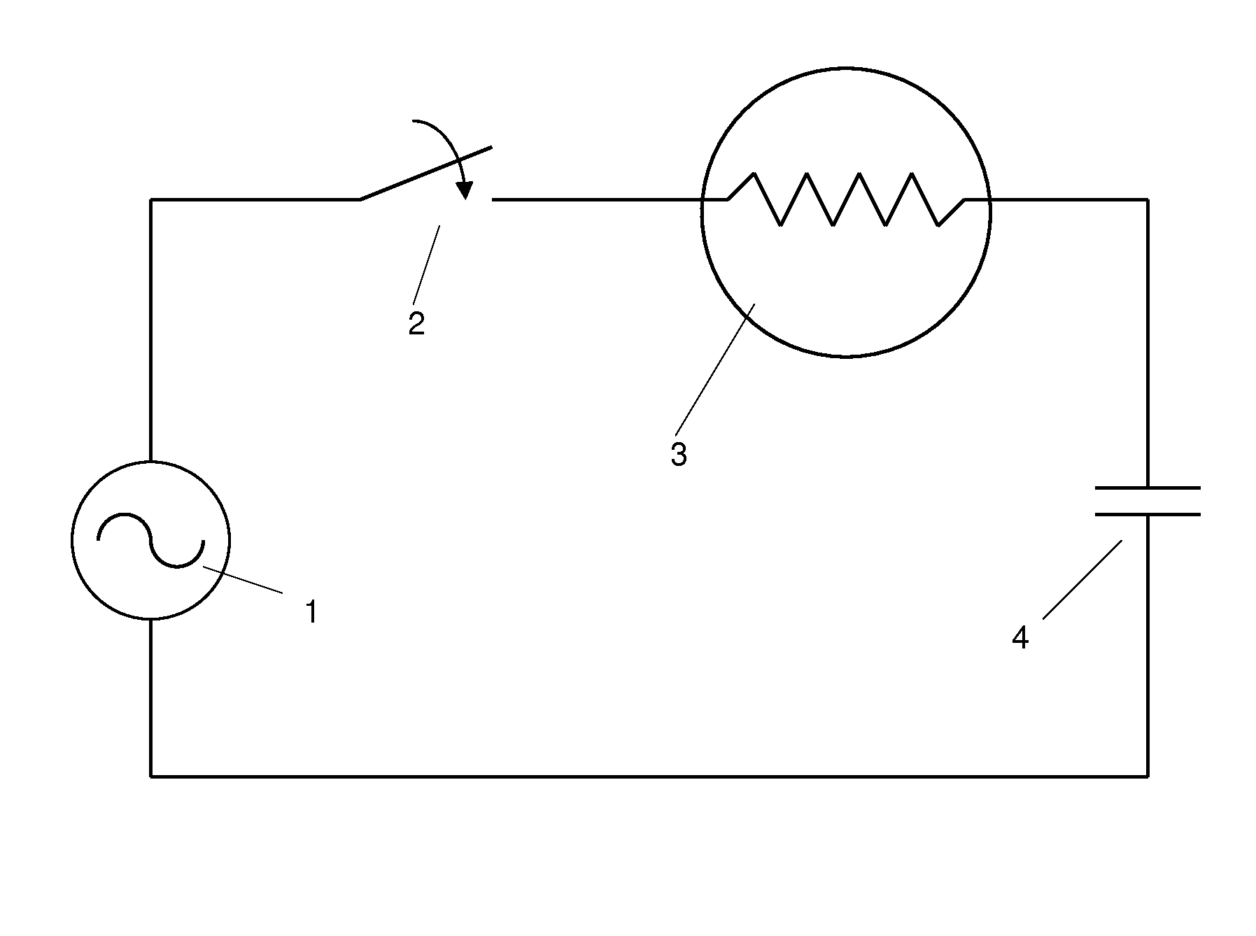
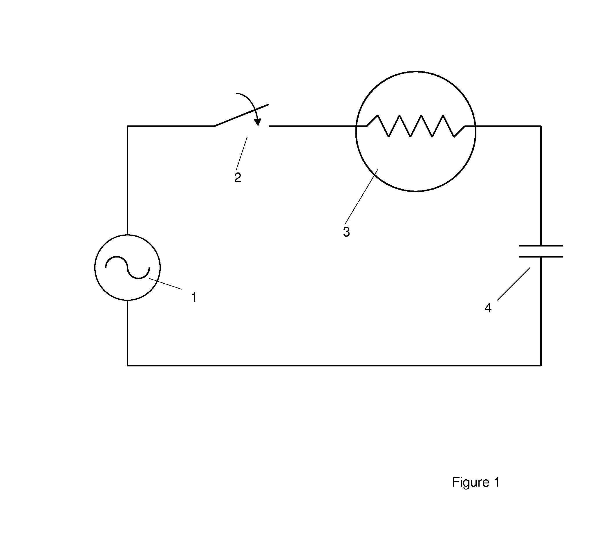
[0007]Protection of a switchgear, such as cirucuit breakers in the switchgear, against the so called “spot welding” under high inrush current load with pre-arcing is disclosed, such as can occur during a closing operation.

[0008]In an exemplary switchgear used for switching capacitive or inductive equipment or inductive or capacitive current networks, an inrush current limiter is placed electrically in line or in series with a current path of the circuit breaker. By this, the current is automatically limited during a switching (closing operation) process, in order to protect the contacts from strong spot welding, in a very effective way.

[0009]Exemplary embodiments can thus reduce the “spot welding strength” during the closing operation by applying an inrush current limiting system. The inrush current limiter can absorb high amounts of inrush current when electrical equipment is turned on, by offering a high resistance to current and quickly decreasing in resistance once steady state ...


PUM


Abstract

A low-, medium-, or high-voltage voltage switchgear with a circuit breaker or circuit breakers is disclosed which can switch electrical equipment. To protect the switchgear, and the cirucuit breakers in the switchgear against so called spot welding under vacuum atmosphere, such as during a closing operation of a switchgear used, for example, for switching capacitive or inductive equipment or inductive or capacitive current network an inrush current limiter is placed electrically in line or in series with the current path of the circuit breaker.

Description

RELATED APPLICATION[0001]This application claims priority as a continuation application under 35 U.S.C. §120 to PCT / EP2012 / 005229, which was filed as an International Application on Dec. 18, 2012 designating the U.S., and which claims priority to European Application 11010183.9 filed in Europe on Dec. 23, 2011. The entire contents of these applications are hereby incorporated by reference in their entireties.FIELD[0002]The present disclosure relates to a switchgear, such as low-, medium-, or high-voltage switchgear.BACKGROUND INFORMATION[0003]A vacuum circuit breaker can be equiped with mainly one single vacuum interrupter to perform close and open operations. In an exemplary specific case, an inrush current of 5 kA at nearly 400 Hz or 20 kA at nearly 4300 Hz in case of back to back switching can have an influence during closing of the contacts at a rated voltage. At first, before the contacts are closed, it develops a pre-arc short before both contacts touch each other, and during ...

Claims


Application Information

Patent Timeline
IPC IPC(8): H02H9/00
CPCH02H9/002H02H7/222H02H3/08H02H7/22H01H9/42H01H9/548H02H9/005H02H9/026
Inventor GENTSCH, DIETMAR
Owner ABB (SCHWEIZ) AG
Why Eureka
Try Eureka