
Seal segment

a technology of sealing segments and fibers, applied in the direction of machines/engines, stators, liquid fuel engines, etc., can solve the problems of more difficult crack growth, and achieve the effect of improving the loading performance of fibres and being easy to manufactur

Active Publication Date: 2014-10-02
ROLLS ROYCE PLC
View PDF4 Cites 13 Cited by
  • Summary
  • Abstract
  • Description
  • Claims
  • Application Information

AI Technical Summary

Benefits of technology

This patent text describes how using reinforcing fibers around slots in a composite material can help reduce stress concentrations and prevent cracks from growing. The reinforcing fibers are also positioned in a way that they can withstand bending stresses and resist crack growth. Additionally, the text explains how using ceramic cement to bond sub-components together can make it easier to manufacture the final body portion. Overall, the technical effects of this patent text are improved strength and durability of composite materials.

Problems solved by technology

Further, the fibres tend to lie across the pathway of incipient cracks at the bases of the slots, deflecting and blunting the cracks, and generally making it more difficult for any cracks to grow.

Method used


Image

  • Seal segment
  • Seal segment
  • Seal segment

Examples


Embodiment Construction

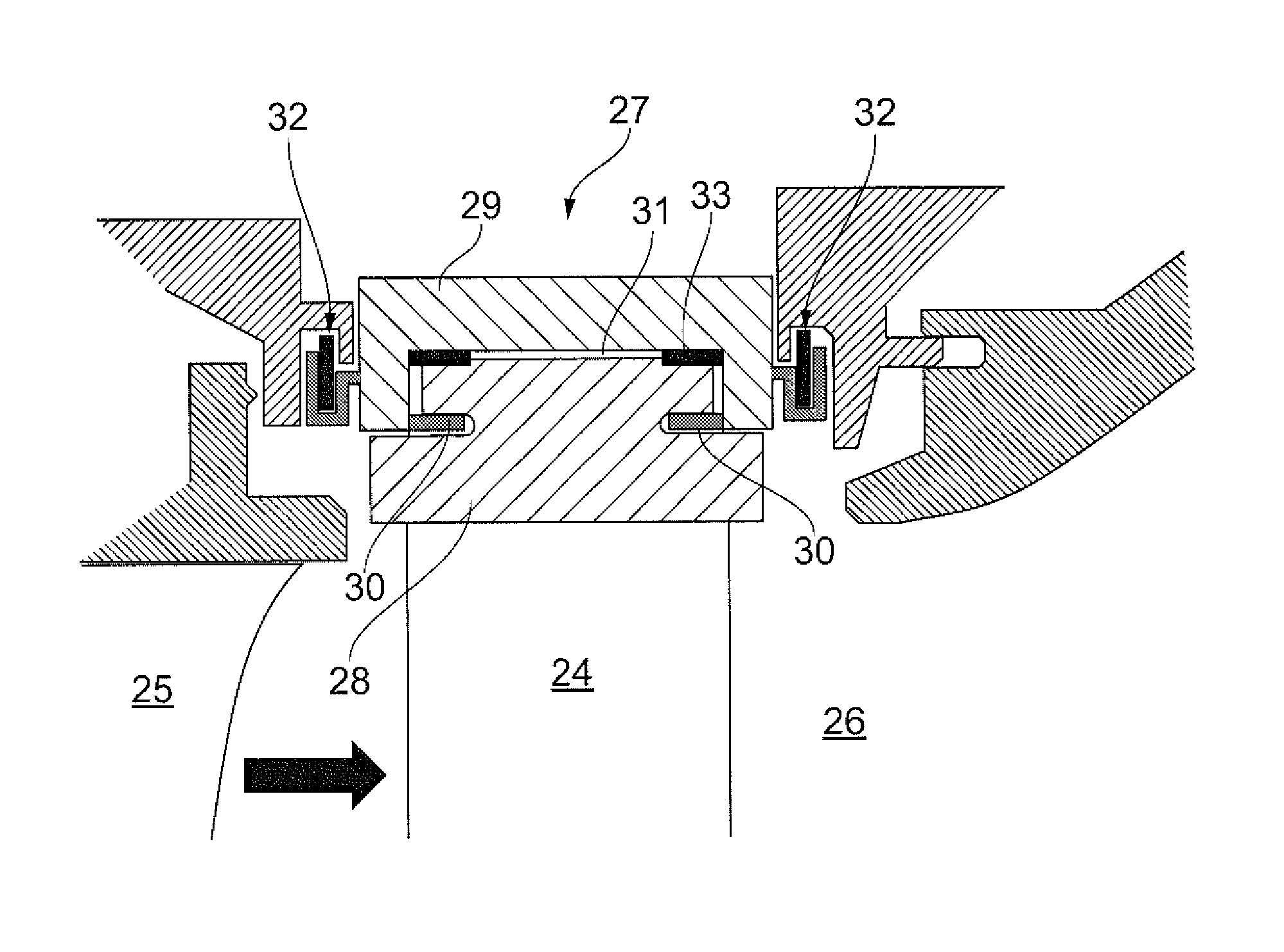
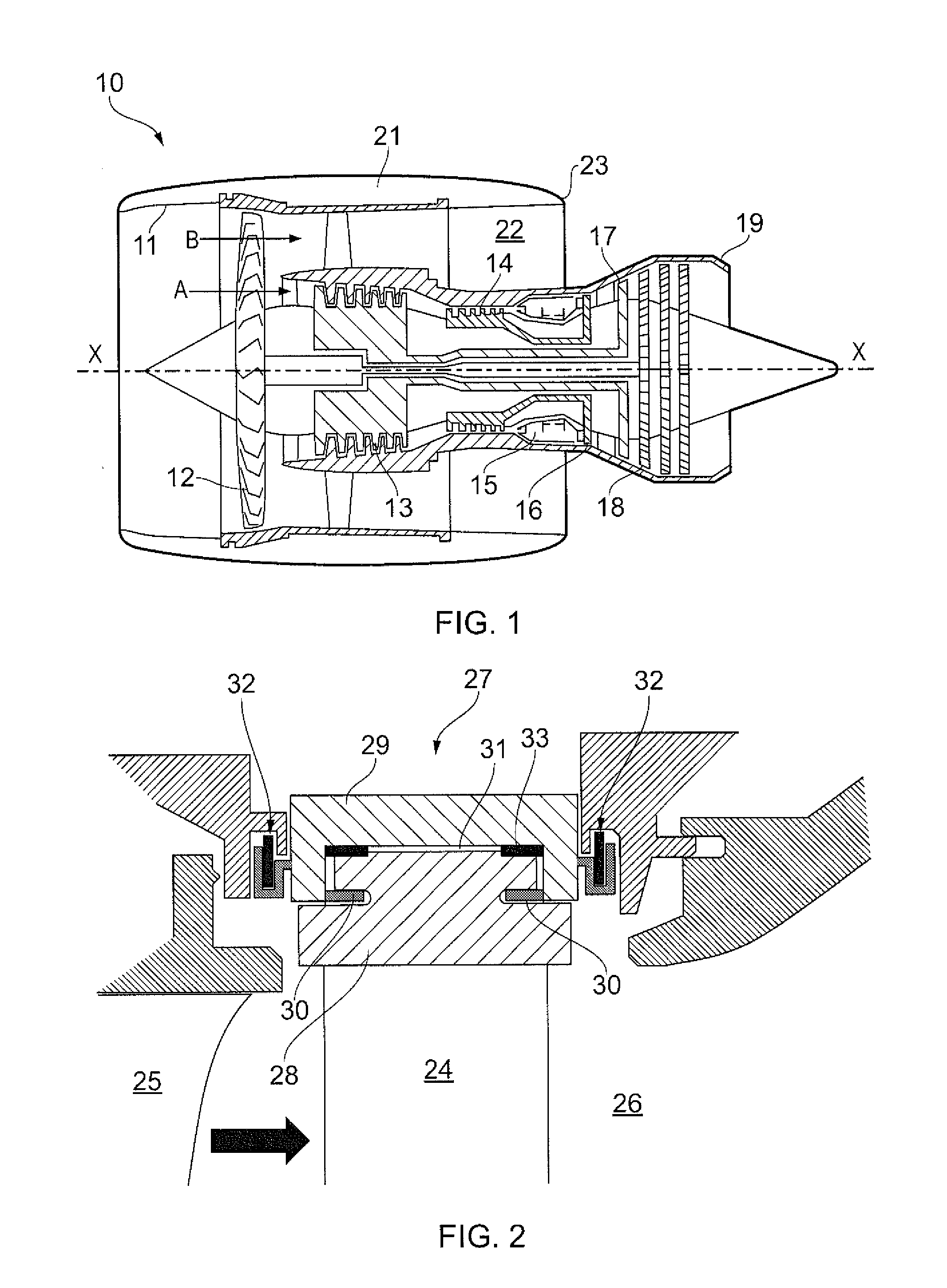
[0027]With reference to FIG. 1, a ducted fan gas turbine engine generally indicated at 10 has a principal and rotational axis X-X. The engine comprises, in axial flow series, an air intake 11, a propulsive fan 12, an intermediate pressure compressor 13, a high-pressure compressor 14, combustion equipment 15, a high-pressure turbine 16, and intermediate pressure turbine 17, a low-pressure turbine 18 and a core engine exhaust nozzle 19. A nacelle 21 generally surrounds the engine 10 and defines the intake 11, a bypass duct 22 and a bypass exhaust nozzle 23.

[0028]The gas turbine engine 10 works in a conventional manner so that air entering the intake 11 is accelerated by the fan 12 to produce two air flows: a first air flow A into the intermediate pressure compressor 13 and a second air flow B which passes through the bypass duct 22 to provide propulsive thrust. The intermediate pressure compressor 13 compresses the air flow A directed into it before delivering that air to the high pre...


PUM


Abstract

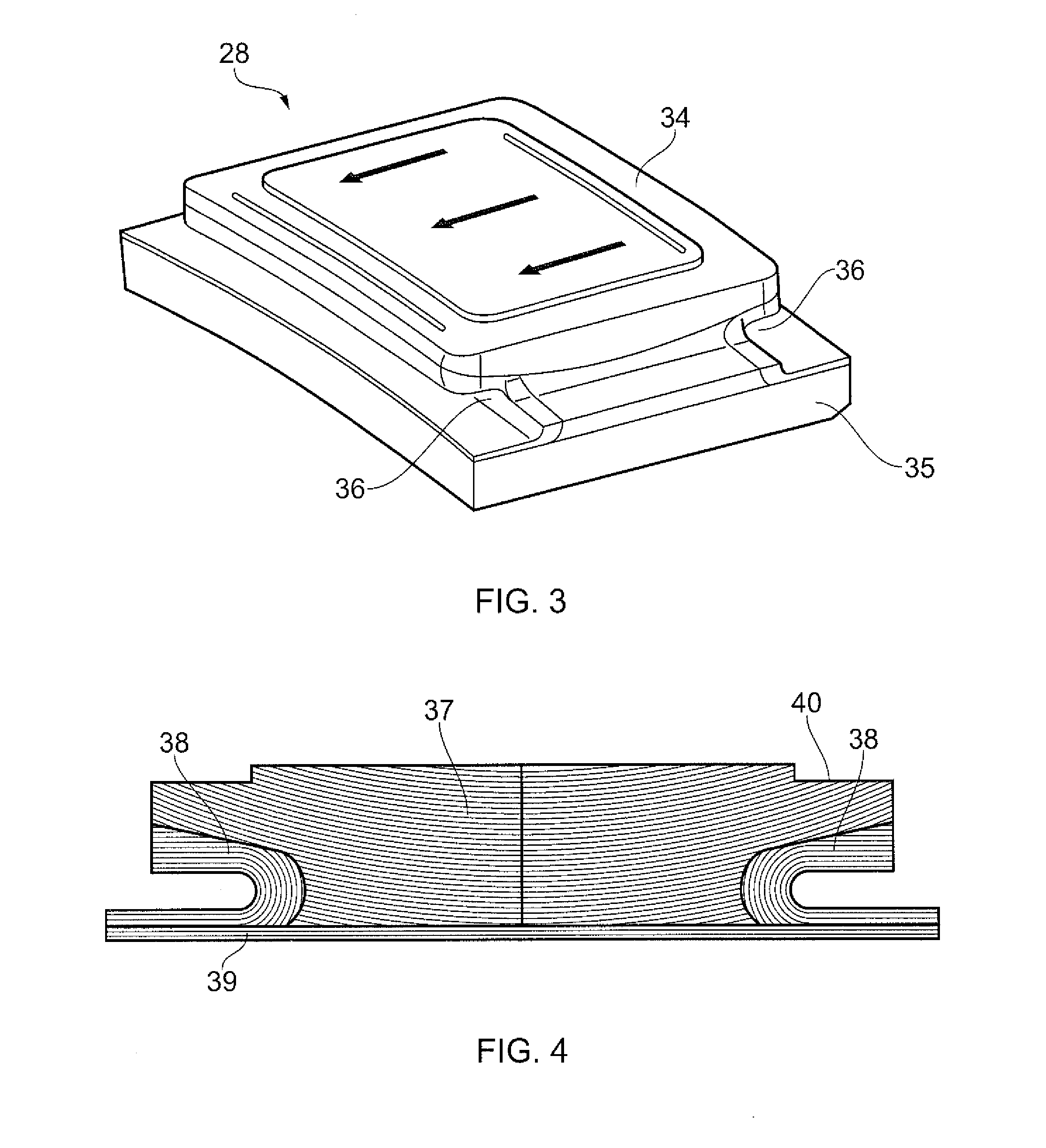
A seal segment is provided for a shroud ring of a rotor of a gas turbine engine. The seal segment is positioned, in use, radially adjacent the rotor. The seal segment includes a body portion having front and rear sides which each contain a respective slot that extends in the circumferential direction so that a respective hook formation is insertable into each slot for attaching the seal segment to the engine casing. The body portion is formed from continuous fibre reinforced ceramic matrix composite, reinforcing fibres of the composite wrapping around each slot so that, at the base of the slot, the reinforcing fibres are parallel to the surface of the body portion.

Description

FIELD OF THE INVENTION[0001]The present invention relates to a seal segment for a shroud ring of a rotor of a gas turbine engine, the segment including a body portion formed from continuous fibre reinforced ceramic matrix composite.BACKGROUND OF THE INVENTION[0002]The performance of gas turbine engines, whether measured in terms of efficiency or specific output, is improved by increasing the turbine gas temperature. It is therefore desirable to operate the turbines at the highest possible temperatures. For any engine cycle compression ratio or bypass ratio, increasing the turbine entry gas temperature produces more specific thrust (e.g. engine thrust per unit of air mass flow). However, as turbine entry temperatures increase, it is necessary to develop components and materials better able to withstand the increased temperatures.[0003]This has led to the replacement of metallic shroud segments with ceramic matrix composite shroud segments having higher temperature capabilities. To ac...

Claims


Application Information

Patent Timeline
Patent Type & Authority Applications(United States)
IPC IPC(8): F01D11/12
CPCF01D11/122F01D5/28F01D5/284F01D9/04F01D11/08F01D25/005Y02T50/60
Inventor HILLIER, STEVEN
Owner ROLLS ROYCE PLC
Learn More