
Image processing for forming realistic stratum detritus detail in a camouflage pattern and a camouflage pattern formed thereby

a camouflage pattern and image processing technology, applied in the field of effective camouflage, can solve the problems of not being able to accurately match the woodland hunting area, and the pattern of camouflage uniforms not being typical

Active Publication Date: 2014-10-02
NTA ENTERPRISES
View PDF2 Cites 5 Cited by
  • Summary
  • Abstract
  • Description
  • Claims
  • Application Information

AI Technical Summary

Benefits of technology

The present invention provides a method for creating realistic hunter camouflage patterns using image processing. The method involves creating a base image layer with a shallow depth of field containing a foreground focal element, adding a lattice work image layer with natural elements, and blending the detritus images into the natural elements of the lattice work. The result is a camouflage pattern that looks natural and includes realistic stratum detritus detail. The technical effects of this method are improved camouflage effectiveness and a more lifelike appearance.

Problems solved by technology

Technological constraints meant that patterned camouflage uniforms were not typically mass manufactured during World War 1. Each patterned uniform of the era was hand-painted, and so restricted to snipers, forward artillery observers, and other exposed individuals.
The divergence of modern hunting camouflage from military camouflage is often attributed to Jim Crumley who reportedly believed he could be more effective at hunting by wearing camouflage that melded with the woodland habitat he hunted and recognized that U.S. military camouflage patterns were designed to match areas where the United States might engage in combat and thus did not adequately match the woodland hunting areas he frequented.

Method used


Image

  • Image processing for forming realistic stratum detritus detail in a camouflage pattern and a camouflage pattern formed thereby
  • Image processing for forming realistic stratum detritus detail in a camouflage pattern and a camouflage pattern formed thereby
  • Image processing for forming realistic stratum detritus detail in a camouflage pattern and a camouflage pattern formed thereby

Examples


Embodiment Construction

[0023]As described in detail below, image processing according to the invention forms realistic stratum detritus detail in a camouflage pattern 10 allowing for the development of effective hunter camouflage patterns 10. The patterns 10 of the invention are camouflage patterns including realistic stratum detritus detail in the camouflage pattern 10 as opposed to a “disruptive” camouflage patterns that tend not to include discernible images or elements but rather break up or disrupt the perceived outline of the subject (e.g. a ghillie suit).

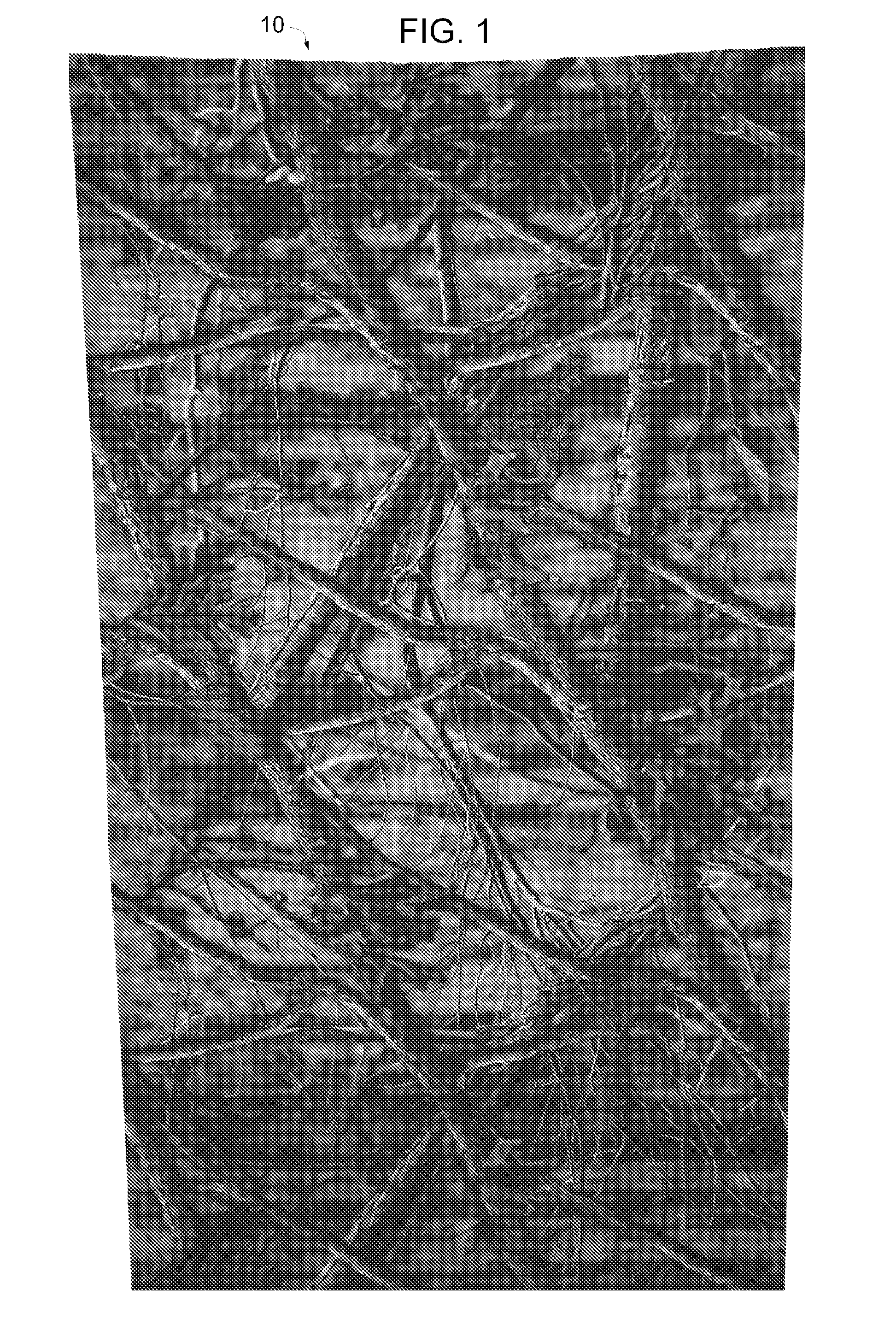
[0024]FIG. 1 is a schematic image of a representative camouflage pattern 10 formed by the image processing according the present invention. The camouflage pattern 10 is formed of realistic photographic images, processed as described below, of natural elements found in the environment associated with the specific pattern 10. For example the pattern 10 shown is a woodland setting or genre and the image elements are those found in the woodland setting...


PUM


Abstract

An image processing method forming realistic stratum detritus detail in a camouflage pattern comprises the steps of: Identifying the desired camouflage genre; Forming a base image layer with a shallow depth of field which includes a foreground focal element extending substantially across the width of the pattern; Forming a lattice work image layer including a lattice work of appropriate natural elements; Overlaying the lattice work image layer onto the base image layer; and Blending the detritus images into the natural elements of the lattice work. Camouflage patterns formed according to the disclosed process are also disclosed which form a more effective hunter camouflage pattern.

Description

RELATED APPLICATIONS[0001]This application claims the benefit of provisional patent application Ser. No. 61 / 727,879 filed Nov. 19, 2012 entitled “Image Processing for Forming Realistic Stratum Detritus Detail in a Camouflage Pattern and a Camouflage Pattern Formed Thereby”.BACKGROUND OF THE INVENTION[0002]1. Field of the Invention[0003]The present invention relates to forming effective camouflage and more specifically to image processing for forming realistic stratum detritus detail in a camouflage pattern and a camouflage pattern formed thereby.[0004]2. Background Information[0005]A quick history of camouflage will often delves through the military applications of camouflage. It has been noted that in feudal Japan, Ninjas in the 14th century used mostly dark camouflage colors during their operations which normally occurred from dusk till dawn. Other times, when the occasion warrants the ninja was known to don suitable cover clothing to blend with the operating environment. In the w...

Claims


Application Information

Patent Timeline
IPC IPC(8): G06T11/60G06K9/46G06V10/40G06V10/56
CPCG06T11/60G06K9/46G06K9/4652G06T11/001G06V10/40G06V10/56
Inventor ROSSWOG, MICHAEL ASKOLNICK, KAREN
Owner NTA ENTERPRISES
Learn More