Air intake structure for turbojet engine nacelle

a turbojet engine and air intake structure technology, which is applied in the direction of power plant air intake arrangements, jet propulsion plants, power plant arrangements/mountings, etc., can solve the problems of complex calculations of force paths and dimensioning, large noise in the area the inability to meet the requirements of the air intake structure, etc., to achieve the effect of improving the structural strength of such an air intake structure and improving the acoustic performan

Active Publication Date: 2014-10-02
SAFRAN NACELLES
View PDF9 Cites 3 Cited by
  • Summary
  • Abstract
  • Description
  • Claims
  • Application Information

AI Technical Summary

Benefits of technology

[0019]There is therefore a need to improve the structural strength of such an air intake structure and to allow the use of at least part of the air intake lip zone in order to improve the acoustic performances by providing it with an acoustic attenuation structure extending the one of the internal wall.

Problems solved by technology

It is therefore situated in a significant noise zone.
Due to the thickness of the acoustic attenuation structure, this connection presents many implementation difficulties.
There are also solutions with solid and acoustic operational skins but calculations of force paths and of dimensioning are more complex.
Because of these geometric constraints, the crank is structurally difficult to achieve and thus impacting the mass of the unit.

Method used


Image

  • Air intake structure for turbojet engine nacelle
  • Air intake structure for turbojet engine nacelle
  • Air intake structure for turbojet engine nacelle

Examples


Embodiment Construction

[0039]The following description is merely exemplary in nature and is not intended to limit the present disclosure, application, or uses. It should be understood that throughout the drawings, corresponding reference numerals indicate like or corresponding parts and features.

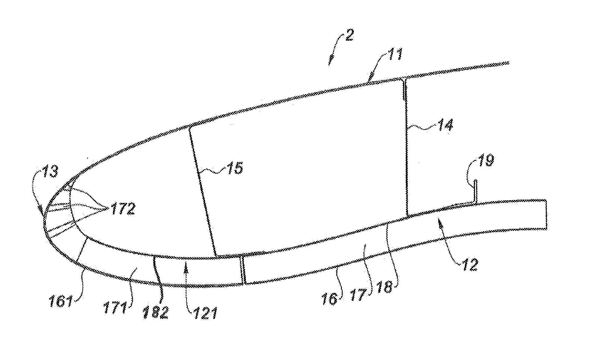
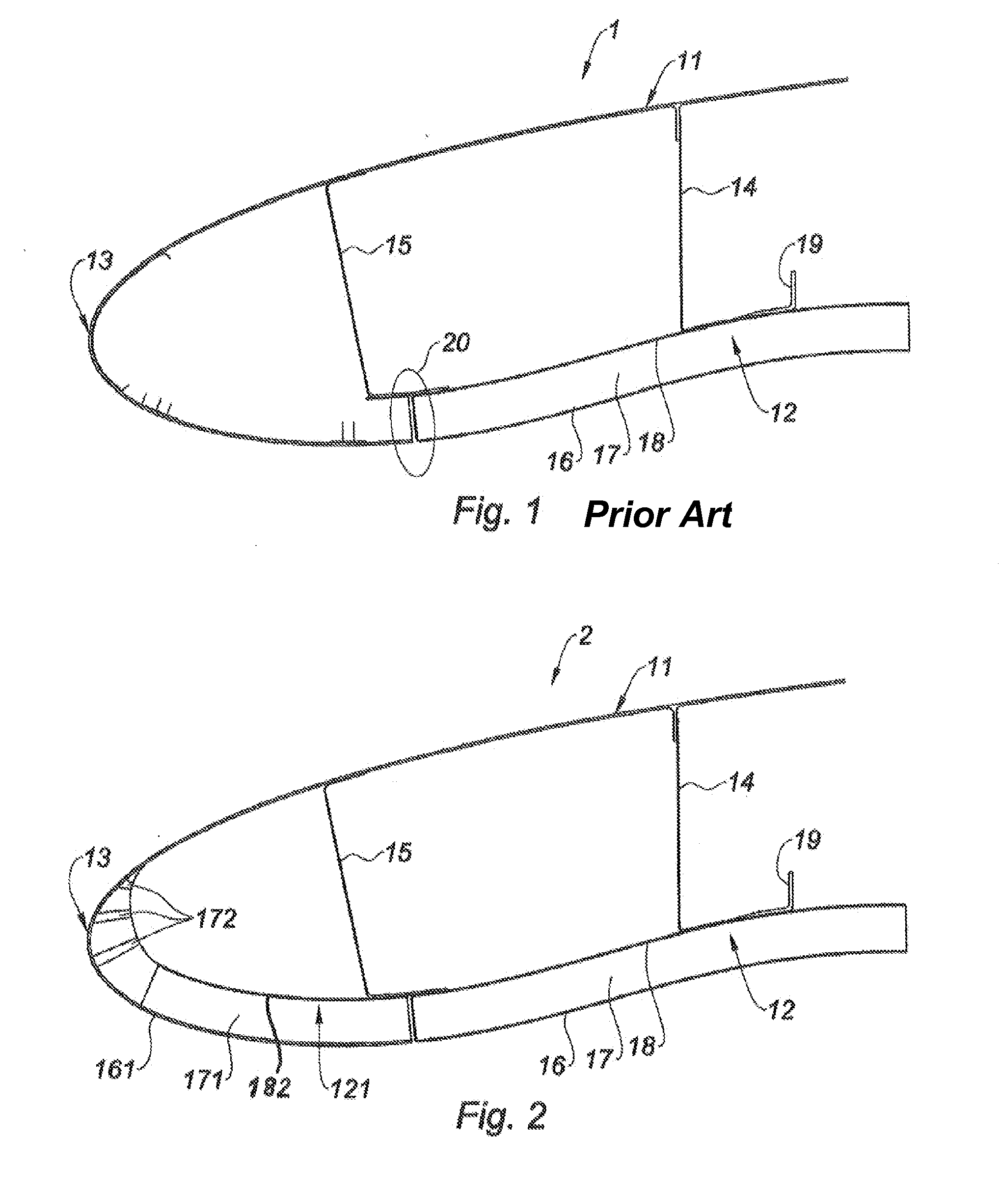
[0040]As represented in FIG. 1, an air intake structure 1 according to the prior art has a substantially annular structure comprising an external wall 11, intended to provide the external aerodynamic continuity with the rest of the nacelle downstream (not represented) and an internal wall 12 intended to provide the internal aerodynamic continuity of the nacelle with a fan casing.

[0041]The external wall 11 and the internal wall 12 are connected upstream with an air intake lip 13 wall forming a leading edge of the nacelle.

[0042]The interior holding of the various walls 11, 12, 13 is done using partitions. There is, in particular, a downstream partition 14 substantially near a connection with the fan casing and an up...


PUM


Abstract

An air intake structure for a turbojet engine nacelle includes a substantially annular main structure having an internal wall, an external wall and an air intake lip structure connecting the external and internal walls upstream. The air intake structure also includes a first acoustic attenuation structure which has a holed acoustic skin, a cellular core and a solid rear skin with which the internal wall is equipped, and a second acoustic attenuation structure having a similar architecture fitted to a part of the air intake lip substantially near a junction with the internal wall. The rear skin of the first acoustic attenuation structure is aligned with the rear skin of the second acoustic attenuation structure, both of rear skins being structural.

Description

CROSS-REFERENCE TO RELATED APPLICATIONS[0001]This application is a continuation of International Application No. PCT / FR2012 / 052836, filed on Dec. 7, 2012, which claims the benefit of FR 11 / 61658, filed on Dec. 15, 2011. The disclosures of the above applications are incorporated herein by reference.FIELD[0002]The present disclosure relates to an air intake structure for a turbojet engine nacelle.BACKGROUND[0003]The statements in this section merely provide background information related to the present disclosure and may not constitute prior art.[0004]An aircraft propulsion unit comprises conventionally a turbojet engine housed inside a nacelle.[0005]The nacelle generally has an annular structure comprising an air inlet upstream of the turbojet engine, a median section intended to surround a fan of said turbojet engine and its casing, and a downstream section intended to surround the combustion chamber of the turbojet engine and enclosing thrust reversal means where necessary. It can ...

Claims


Application Information

Patent Timeline
Patent Type & Authority Applications(United States)
IPC IPC(8): F02C7/045
CPCB64D33/02B64D2033/0286B64D2033/0206F02C7/045
Inventor DEZEUSTRE, NICOLASCARUEL, PIERREGONIDEC, PATRICKBOILEAU, PATRICK
Owner SAFRAN NACELLES
Why Eureka
Try Eureka