
Prediction-based switch allocator

a prediction-based, allocator technology, applied in the direction of digital transmission, data switching network, electrical apparatus, etc., can solve the problems of wasting bandwidth on output links, complex design of switch allocators, and often non-trivial arbitrage calculations

Active Publication Date: 2014-09-18
ORACLE INT CORP
View PDF6 Cites 6 Cited by
  • Summary
  • Abstract
  • Description
  • Claims
  • Application Information

AI Technical Summary

Benefits of technology

The patent describes an allocation circuit for a switch that uses an arbitration mechanism to determine the mapping of input to output ports. The mechanism maintains a set of mappings for a subset of the input ports and matches other flits associated with other ports to ensure efficient allocation. The outcome of the arbitration process results in a set number of mappings and a solution space that is smaller than the input and output ports. The switch includes a switching mechanism that selectively couples the input ports to the output ports based on the mappings. The method for determining mappings involves maintaining the set of mappings for a preceding cycle and matching other flits to the remainder. This invention optimizes the allocation of resources and improves the performance of the switch.

Problems solved by technology

However, this arbitration calculation is often non-trivial.
Furthermore, design of switch allocators can be complicated by additional factors.
However, design and technology constraints often restrict an input port to transferring at most one flit per arbitration decision cycle, and an output port to accepting at most one flit per arbitration decision cycle.
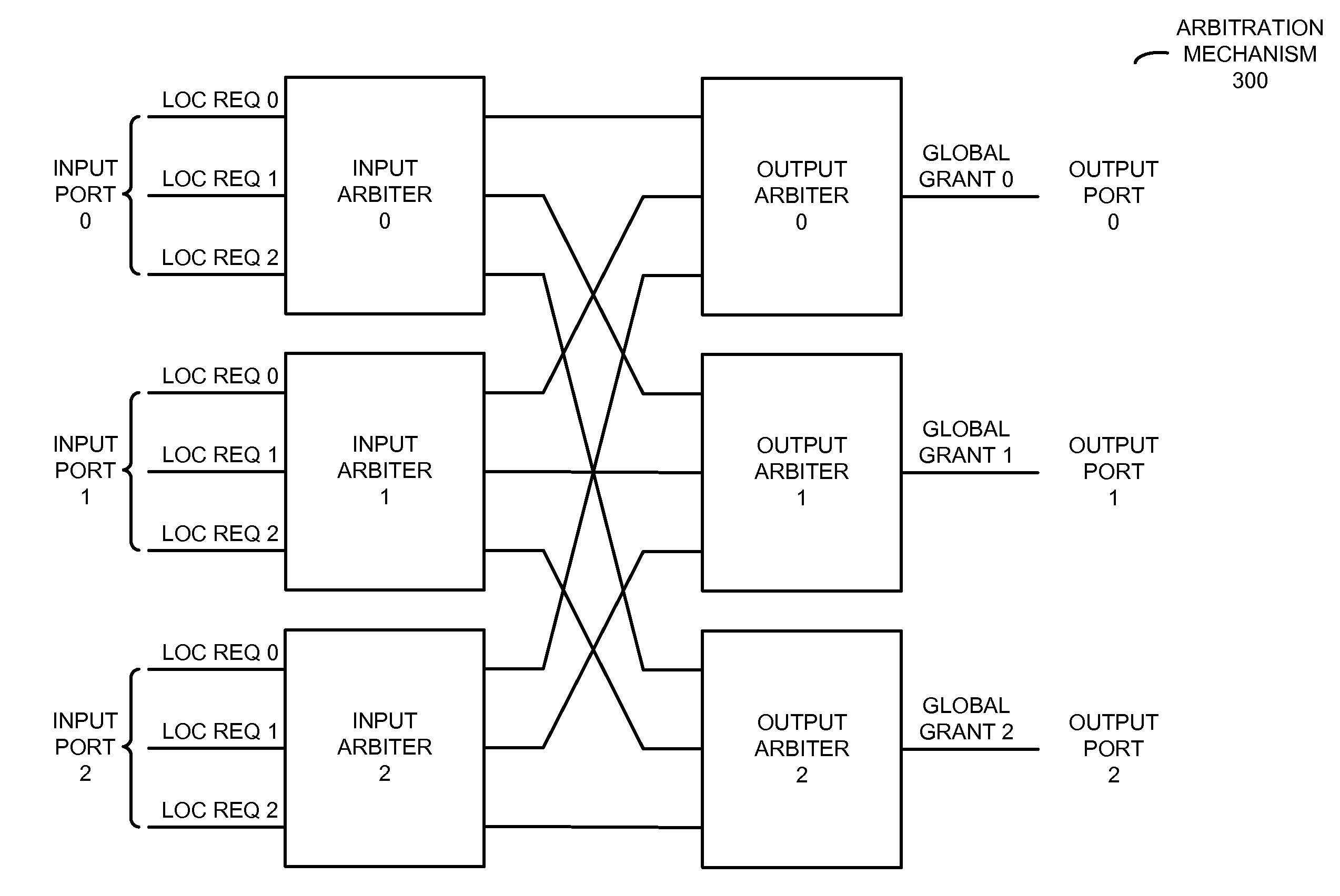
However, at current clock speeds, the switch allocator usually cannot acquire a global snapshot of the input requests within a clock cycle and therefore must resort to distributed arbitration, in which the input and output ports act independently of each other and are agnostic of the decisions of the other input and output ports.
This distributed arbitration often causes conflicts in the port allocation, leading to wasted bandwidth on the output links.
Arbitration collisions such as this typically limit the router throughput and, thus, the overall network performance at high injection loads.
Therefore, it can be difficult for existing switch allocators to balance the conflicting requirements of reducing arbitration collisions while maintaining high throughput.

Method used


Image

  • Prediction-based switch allocator
  • Prediction-based switch allocator
  • Prediction-based switch allocator

Examples


Embodiment Construction

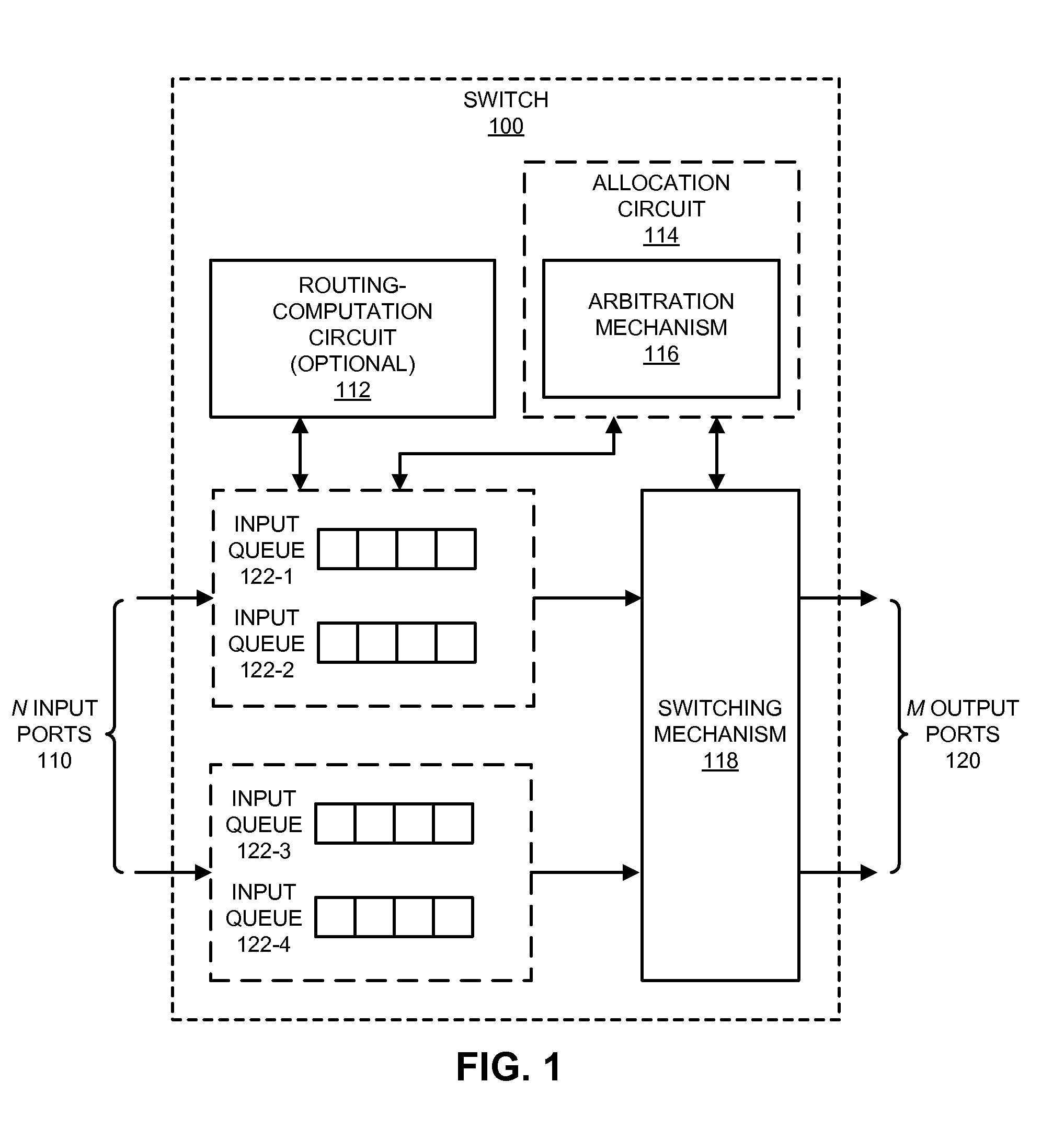
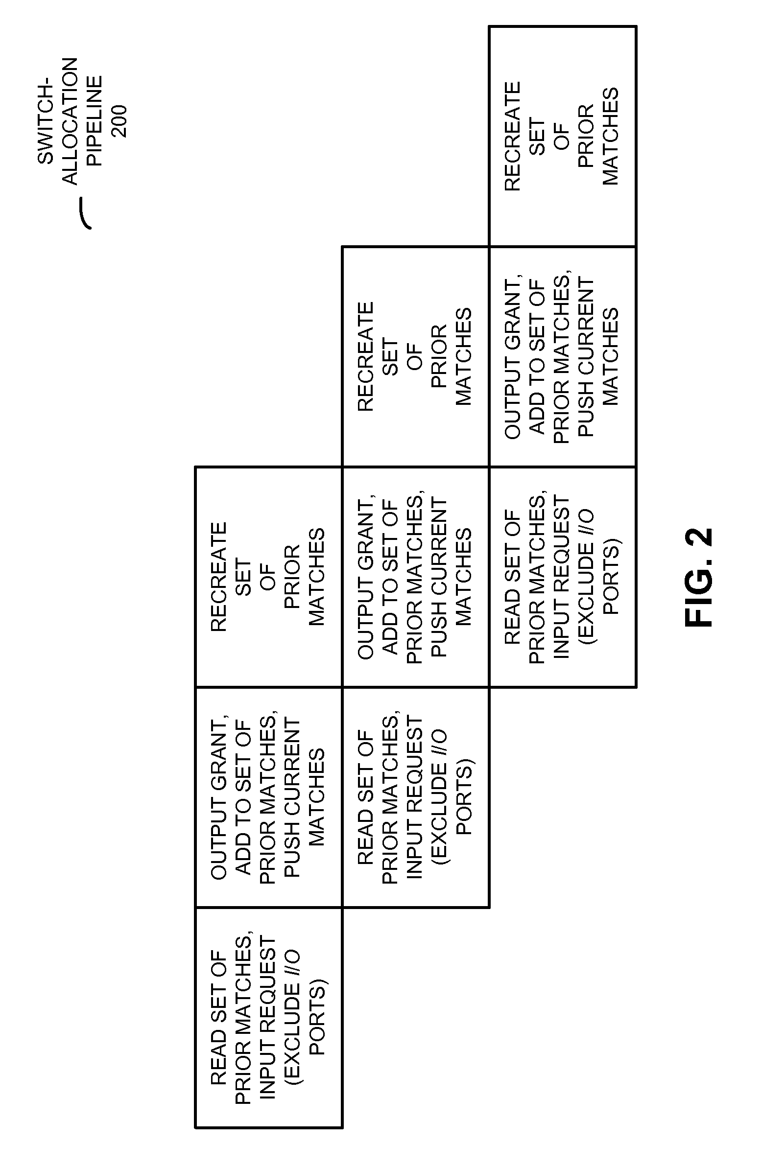
[0029]Embodiments of an allocation circuit with an arbitration mechanism, a switch that includes the arbitration mechanism, and an arbitration technique for determining mappings for the switch are described. During a given arbitration decision cycle, the arbitration mechanism maintains, until expiration, a set of mappings from a subset of the input ports to a subset of the output ports of the switch. This set of mappings was determined during an arbitration decision cycle up to K cycles preceding the given arbitration decision cycle. Because the set of mappings are maintained, it is easier for the arbitration mechanism to determine mappings from a remainder of the input ports to the remainder of the output ports without collisions.

[0030]By introducing memory in the arbitration decision process, the prediction-based arbitration technique can improve router throughput (for example, up to 18%) while reducing arbitration collisions with low router latency. In addition, the arbitration t...


PUM


Abstract

An arbitration technique for determining mappings for a switch is described. During a given arbitration decision cycle, an arbitration mechanism maintains, until expiration, a set of mappings from a subset of the input ports to a subset of the output ports of the switch. This set of mappings was determined during an arbitration decision cycle up to K cycles preceding the given arbitration decision cycle. Because the set of mappings are maintained, it is easier for the arbitration mechanism to determine mappings from a remainder of the input ports to the remainder of the output ports without collisions.

Description

BACKGROUND[0001]1. Field[0002]The present disclosure generally relates to techniques for determining input-output mappings for a switch. More specifically, the present disclosure relates to an arbitration technique that maintains mappings from a preceding arbitration decision cycle.[0003]2. Related Art[0004]On-chip and inter-chip routers accept flits (the logical fragments of a packet) from incoming on-chip network links, examine the destinations of these flits and route them through the appropriate outgoing on-chip network links. A canonical router includes of a set of input ports to accept the incoming flits, a set of output ports to issue the outgoing flits, routing logic to determine the next hop for each flit, a crossbar or switch to transfer flits from the input ports to the output ports and a switch allocator which attempts to create a conflict-free schedule of flits to be transferred on each arbitration decision cycle. Moreover, blocking networks (i.e., networks that do not ...

Claims


Application Information

Patent Timeline
Patent Type & Authority Applications(United States)
IPC IPC(8): H04L12/863
CPCH04L47/6205H04L47/6225H04L49/356H04L49/254
Inventor KOKA, PRANAYSCHWETMAN, JR., HERBERT D.JAFRI, SYED ALI RAZA
Owner ORACLE INT CORP
Learn More