
Turbomachine component monitoring system and method

a technology for monitoring systems and components, applied in the field of power systems, can solve problems such as requiring repair, affecting the efficiency of turbomachine operation, and affecting the structural integrity of buckets, nozzles and/or other components inside the turbomachine,

Inactive Publication Date: 2014-09-18
GENERAL ELECTRIC CO
View PDF9 Cites 32 Cited by
  • Summary
  • Abstract
  • Description
  • Claims
  • Application Information

AI Technical Summary

Benefits of technology

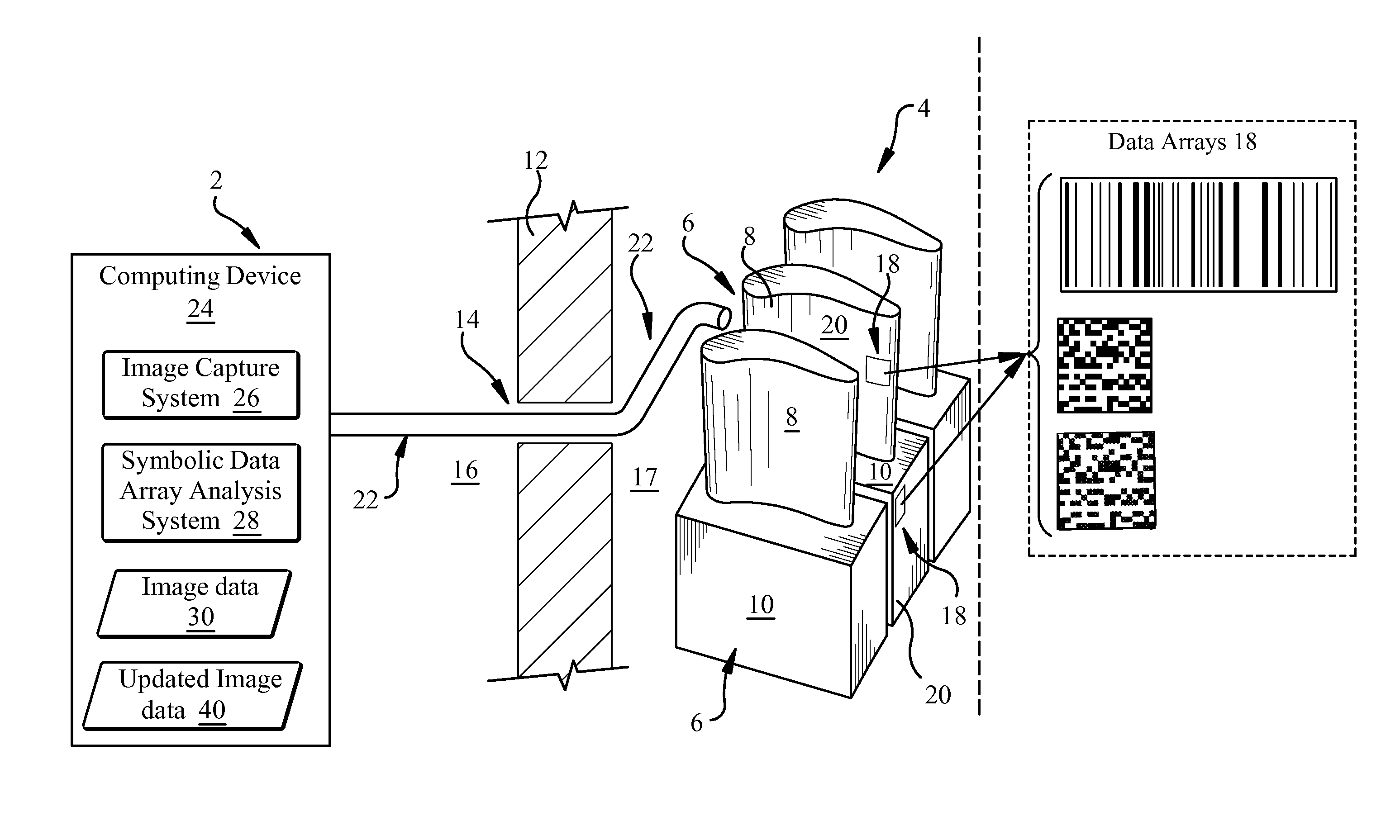
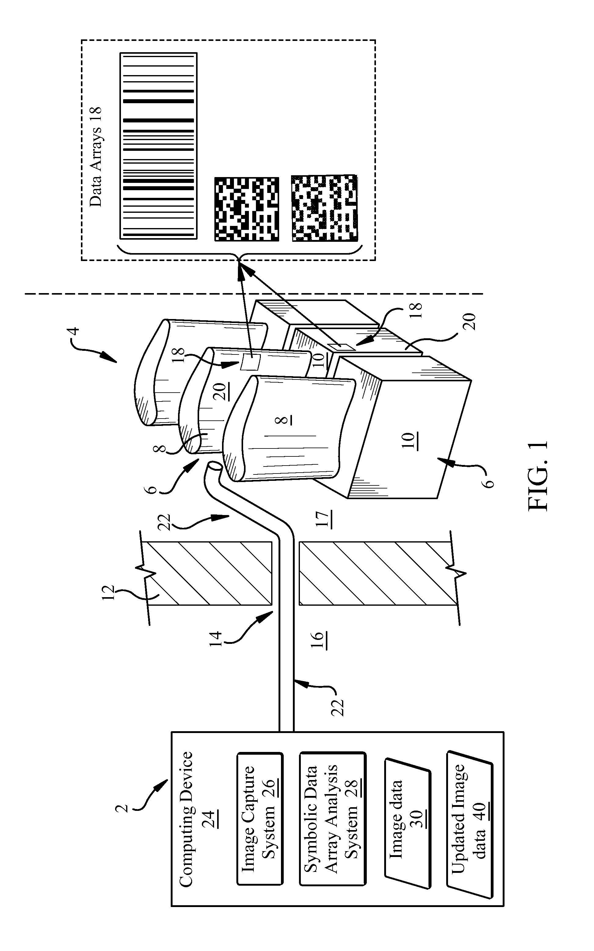
This patent describes a system for monitoring components in a turbomachine. The system includes a borescope probe that can pass through an opening in the turbomachine and detect a symbolic data array on a component within it. An at least one computing device is connected to the borescope probe and can capture image data of the symbolic data array. The image data is then analyzed using a symbolic data array analysis program to determine if it is compatible with the program. The system can also initiate a message if the image data is not compatible with the program. The technical effect of this system is that it allows for efficient and effective monitoring of components in a turbomachine.

Problems solved by technology

During operation of these turbomachines, the rotating buckets and / or static nozzles are subject to intense temperature and pressure conditions which can degrade the structural integrity of the buckets, nozzles and / or other components inside the turbomachine.
These degraded components may cause the turbomachine to run less efficiently, may create safety concerns, and may eventually require repair.
However, due to the fact that these components (e.g., buckets and / or blades) are sealed within the turbomachine during operation, it can be difficult to monitor their condition.

Method used


Image

  • Turbomachine component monitoring system and method
  • Turbomachine component monitoring system and method
  • Turbomachine component monitoring system and method

Examples


Embodiment Construction

[0014]As noted, the subject matter disclosed herein relates to power systems. More particularly, the subject matter relates to monitoring components in turbomachine systems.

[0015]As described herein, conventional turbomachines (also referred to as turbines), such as steam turbines (steam turbomachines) or gas turbines (gas turbomachines), generally include static nozzle assemblies that direct the flow of working fluid (e.g., steam or gas) into rotating buckets that are connected to a rotor. During operation of these turbomachines, the rotating buckets and / or static nozzles are subject to intense temperature and pressure conditions which can degrade the structural integrity of the buckets, blades and / or other components inside the turbomachine.

[0016]These degraded components may cause the turbomachine to run less efficiently, may create safety concerns, and may eventually require repair. Monitoring these components can be helpful to anticipate degradation and repair. However, due to ...


PUM


Abstract

Various embodiments include approaches for monitoring turbomachine components. In various particular embodiments, a system for monitoring a component within a turbomachine includes: a borescope probe sized to pass through an opening in the turbomachine, the borescope probe for detecting a symbolic data array on the component within the turbomachine; and at least one computing device operably coupled to the borescope probe, the at least one computing device configured to: obtain image data about the symbolic data array from the borescope probe; evaluate the image data to determine whether the image data is compatible with a symbolic data array analysis program; and analyze the image data using the symbolic data array analysis program in response to determining the image data is compatible with the symbolic data array analysis program.

Description

FIELD OF THE INVENTION[0001]The subject matter disclosed herein relates to power systems. More particularly, the subject matter relates to monitoring components within turbomachine systems.BACKGROUND OF THE INVENTION[0002]Conventional turbomachines (also referred to as turbines), such as steam turbines (steam turbomachines) or gas turbines (gas turbomachines), generally include static nozzle assemblies that direct the flow of working fluid (e.g., steam or gas) into rotating buckets that are connected to a rotor. During operation of these turbomachines, the rotating buckets and / or static nozzles are subject to intense temperature and pressure conditions which can degrade the structural integrity of the buckets, nozzles and / or other components inside the turbomachine.[0003]These degraded components may cause the turbomachine to run less efficiently, may create safety concerns, and may eventually require repair. Monitoring these components can be helpful to anticipate degradation and r...

Claims


Application Information

Patent Timeline
Patent Type & Authority Applications(United States)
IPC IPC(8): G06T7/00G02B23/24
CPCG02B23/2484G06T7/0004G01M5/0016G01M5/0033G01M5/0091
Inventor WARD, JR., JOHN DAVIDBATZINGER, THOMAS JAMESJANAWITZ, JAMISON WILLIAMTHOMPSON, CHRISTOPHER EDWARD
Owner GENERAL ELECTRIC CO
Learn More