
Substrate processing apparatus

a substrate processing and substrate technology, applied in the direction of liquid surface applicators, instruments, coatings, etc., can solve the problems of reattaching process liquid onto the substrate, increasing the height unable to move the supply target position of process liquid, so as to reduce the running cost of the substrate processing apparatus, and reduce the amount of process liquid

Active Publication Date: 2014-09-18
DAINIPPON SCREEN MTG CO LTD
View PDF7 Cites 10 Cited by
  • Summary
  • Abstract
  • Description
  • Claims
  • Application Information

AI Technical Summary

Benefits of technology

The patent describes a substrate processing apparatus that reduces the reattachment of process liquid onto the substrate, which can cause contamination. This is achieved by designing a collection groove that prevents liquid droplets from diffusing and a guide member that controls the splashing directions of process liquid. By controlling the area where process liquid splashes, the apparatus reduces the amount of process liquid needed and decreases reattachments of process liquid, ultimately reducing running costs.

Problems solved by technology

In contrast, in case when directions of splashes of process liquid from peripheral part of the substrate are obliquely upward, droplets or mist of process liquid move in directions inward and obliquely downward toward the upper face of the substrate, thus may resulting in reattachments of process liquid onto the substrate.
However, in the case of this substrate processing apparatus, because the whole area of the upper face of the substrate is covered by the atmosphere blocking plate, it is not possible to move supply target positions of process liquid toward the upper face of the substrate between the central and peripheral part of the substrate.
Also, because of the space required to make in order to move the atmosphere blocking plate up and down above the substrate, compared to configurations without such atmosphere blocking plate, height of the substrate processing apparatuses become larger.

Method used


Image

  • Substrate processing apparatus
  • Substrate processing apparatus
  • Substrate processing apparatus

Examples


Embodiment Construction

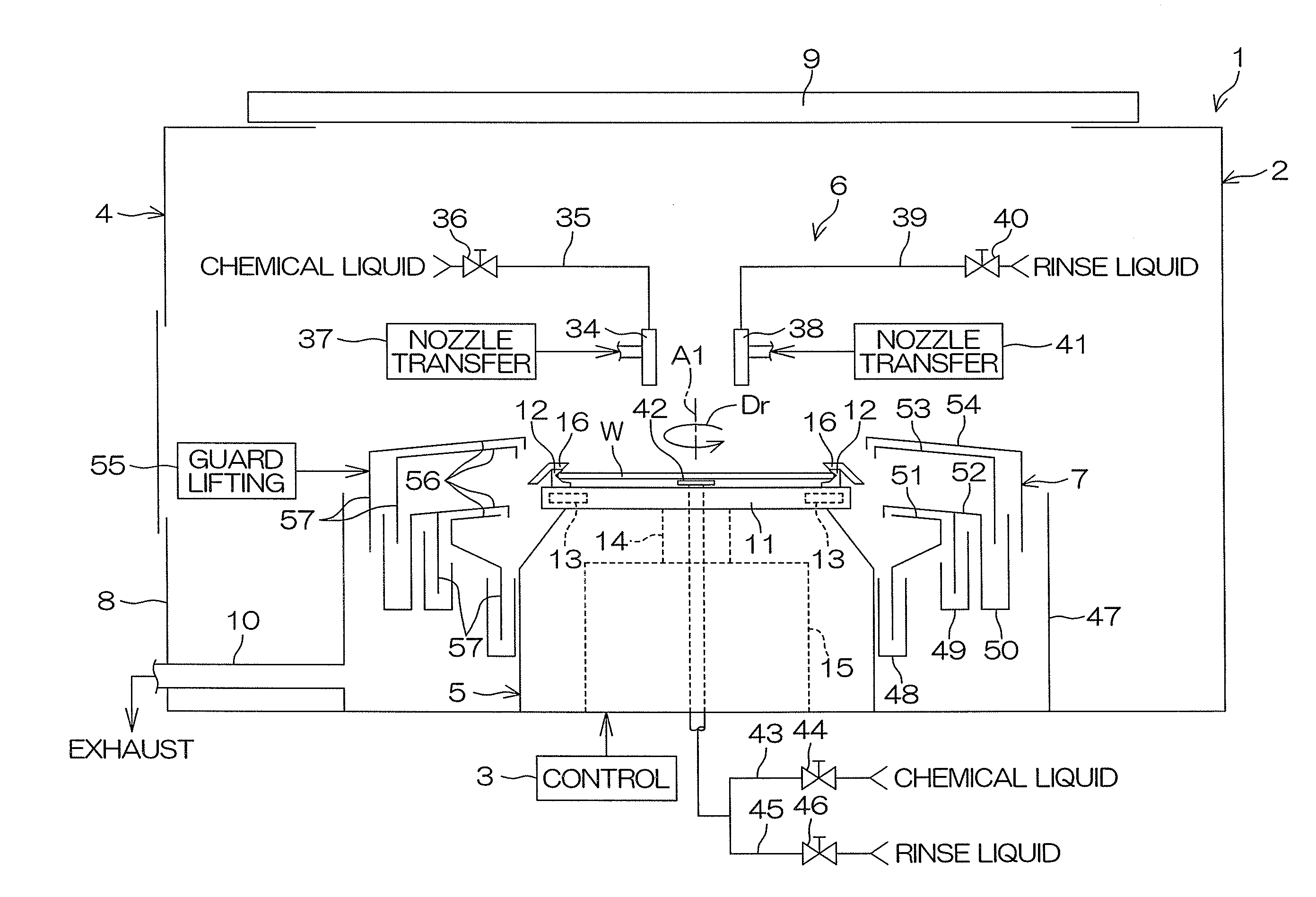
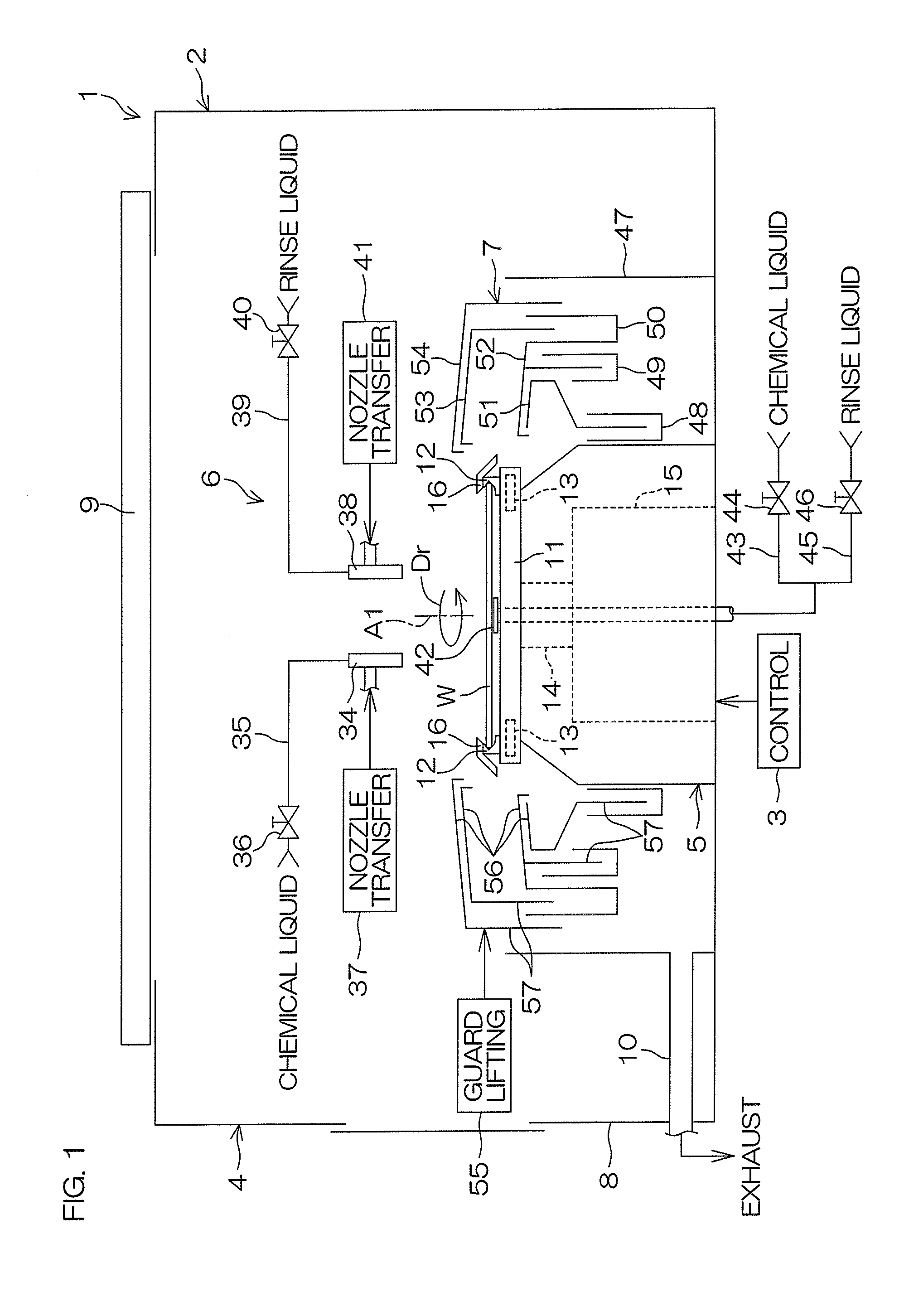
[0045]FIG. 1 is a schematic view showing the inside configuration of a chamber comprised in a substrate processing apparatus according to a preferred embodiment. FIG. 2 is a schematic plan view of a spin chuck. FIG. 3 is a schematic plan view of the chuck pin and a guide member. FIGS. 4A and 4B are, respectively, a schematic plan view showing the chuck pin is positioned at a close position, and a schematic plan view showing the chuck pin is positioned at an open position. FIG. 5 is a vertical cross-sectional schematic view of the chuck pin and the guide member. As shown in FIGS. 4A and 4B, the chuck pin 12 can move between a close position (shown in FIG. 4A) and an open position (shown in FIG. 4B). Hereinafter, unless otherwise specified, illustration will be made in a condition that the chuck pin 12 is positioned at the close position.

[0046]As is shown in FIG. 1, a substrate processing apparatus 1 is an apparatus of single substrate processing type that processes circular substrate...


PUM


Abstract

A substrate processing apparatus for processing a substrate comprises: a plurality of chuck pins each having an accommodating groove for accommodating a portion of peripheral part of the substrate, holding the substrate at a hold position in a horizontal posture by pressing inner faces of the accommodating grooves toward portions of peripheral part of the substrate; and a plurality of guide members, being disposed on or above the respective plurality of chuck pins, guiding process liquid discharged from the substrate to a surrounding area of the substrate; wherein each of the plurality of guide member includes: an inner-edge guide disposed at a position inward and above the accommodating groove; and an outer-edge guide disposed at a position level with or below the inner-edge guide and outward the chuck pin.

Description

BACKGROUND OF THE INVENTION[0001]1. Field of the Invention[0002]The present invention generally relates to a substrate processing apparatus for processing substrates with process liquids. Examples of substrates to be processed include semiconductor wafers, glass substrates for liquid crystal displays, glass substrates for plasma displays, substrates for FEDs (field emission displays), substrates for optical discs, substrates for magnet discs, substrates for magnet-optical discs, glass substrates for photomasks, substrates for ceramics, substrates for solar cells, etc.[0003]2. Description of Related Art[0004]In the manufacturing process of semiconductor or liquid crystal display apparatus, substrate processing apparatuses of single substrate processing type for processing substrates one-by-one basis or substrate processing apparatuses of batch type for processing substrates in a lump are used.[0005]The substrate processing apparatus of single substrate processing type described in U....

Claims


Application Information

Patent Timeline
Patent Type & Authority Applications(United States)
IPC IPC(8): B05C5/02
CPCB05C5/02H01L21/67051H01L21/68728G03F7/162G03F7/3021H01L21/6715
Inventor YAMAGUCHI, TAKAHIRO
Owner DAINIPPON SCREEN MTG CO LTD
Learn More