
Socket switch

a socket switch and socket technology, applied in the field of sockets, can solve the problems of reducing causing electrocution hazards, so as to prolong the life of replacement parts, minimise wear through rotation, and enhance the compact size of inventive arrangements

Inactive Publication Date: 2014-09-18
FLETCHER NICHOLAS
View PDF15 Cites 9 Cited by
  • Summary
  • Abstract
  • Description
  • Claims
  • Application Information

AI Technical Summary

Benefits of technology

The arrangement described in the patent text has a simplified design to save money and increase durability. It includes guides made of cavities and crimps that hold plug pins in place and prevent accidental displacement. The guides can be in the form of contoured slots or spiral springs. The arrangement also has a bias that helps balance rotational forces and extend the life of the parts. Overall, this design reduces production times, minimizes manufacturing costs, and improves durability for high-speed operation and long-term use.

Problems solved by technology

This can create a potential hazard where a power socket is rendered live by activating the switch with no electric plug covering the socket terminals.
Not only may a small child dangerously insert a conductible element into a live socket, but splashed or rising water, for example in a localised flood situation, may create an electrocution hazard by allowing the possibility for live terminals to be exposed.
However, because this prior art attempt requires that the plug receptacle 8 be axially slidable to allow rotation about its axis, it can prove more difficult for persons lacking dexterity, for example the aged or infirm, to manipulate the electric plug to the active position.

Method used


Image

  • Socket switch
  • Socket switch
  • Socket switch

Examples


second embodiment

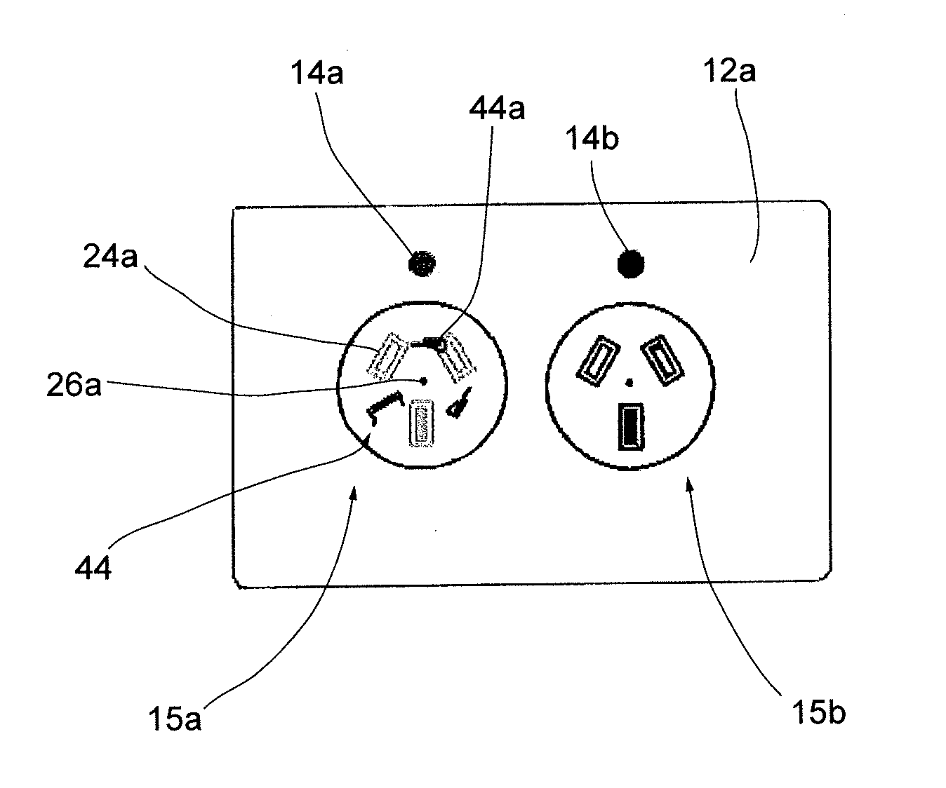
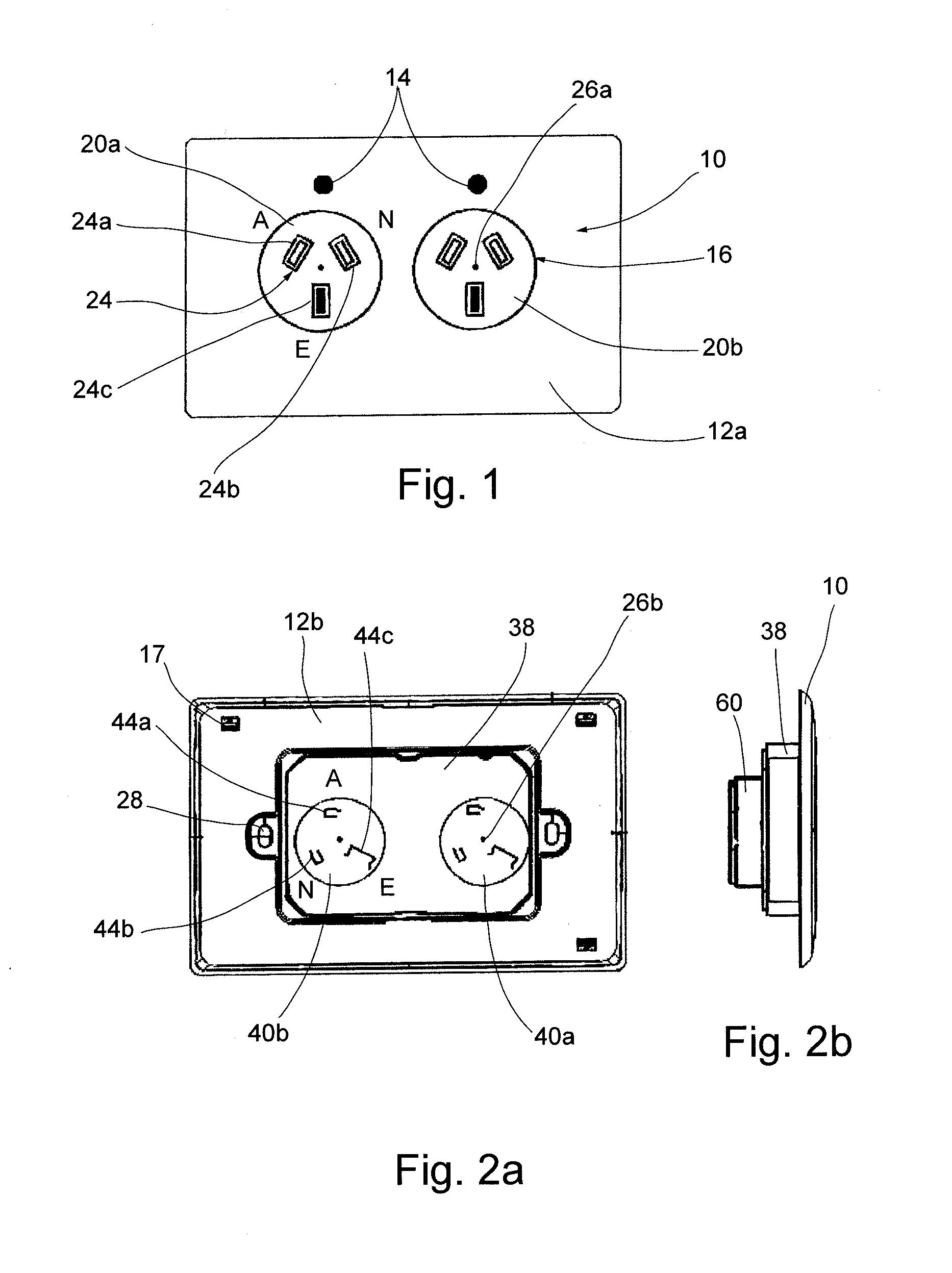
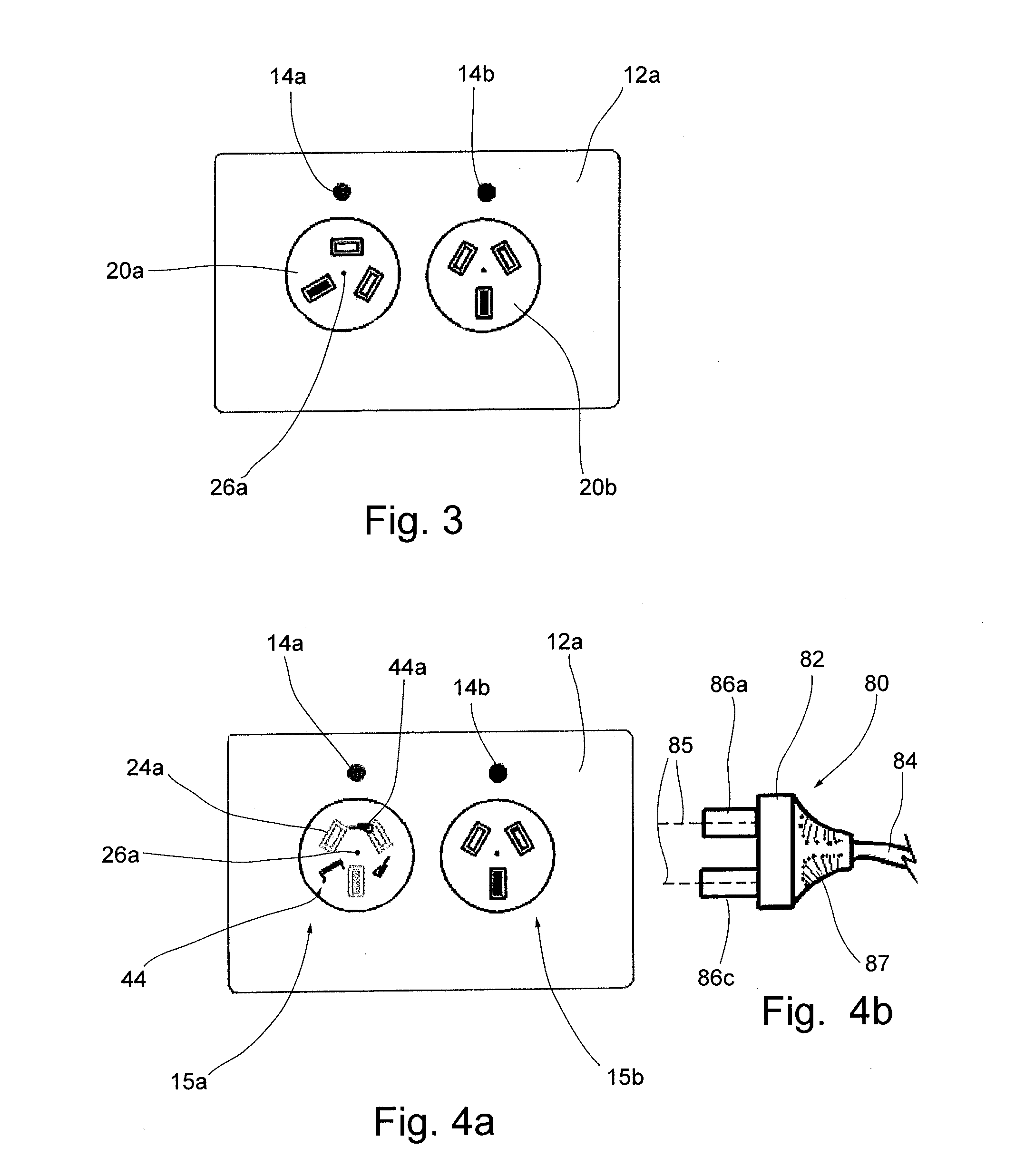
[0085]In FIG. 5, there is shown the front panel 12a of a socket switch casing 10a according to this disclosure. The socket switch housing 10a comprises a pair of first and second sockets 15a, 15b.

[0086]The sockets 15a, 15b have a corresponding pair of rotatable disc housings 20 comprising an outer hollow cylindrical disc 21a, 21b adapted to rotatably fit in the cylindrical cavity 16 and defining an inner cylindrical cavity 23 into which is inserted an insert aperture body 22. The insert 22 is an aperture body including an array of apertures for receiving plug pins according to any one of a range of pin configurations. The insert aperture body 22 may be varied from jurisdiction to jurisdiction or from one socket type to another to accommodate different socket types. The socket casing 10a may be provided with a variety of possible insert aperture bodies 22 to adapt the socket casing 10a to any one of a variety of socket plug arrangements, including types A-M listed below.

[0087]With r...

fourth embodiment

[0097]Referring to FIGS. 11 to 12e, there is shown a fourth embodiment having a pair of pivot detent locks 57, 58 pivotally mounted to the respective walls of the active and neutral crimps 42a, 42b. Of course, the skilled person will appreciate that the arrangement may operate with only one detent 57 or detent 58 acting in relation to either the active crimp 42a or the neutral crimp 42b, respectively. The components described with reference to these drawings will be described by reference to the rotating body 20 being uppermost and lying in a horizontal plane.

[0098]The pivot detent locks 57, 58 comprise a solid body or block that is pivotally spring mounted about a hinge by a spring 59. The spring may be formed of metal or plastic and may be formed integrally with the fixed body or the lock 57, 58. Preferably, the spring 59 is formed from plastic and attached or integrally formed with an internal wall of the active or neutral crimp 42a, 42b near the pin entry zone 45a, 45b.

[0099]Th...

fifth embodiment

[0111]As shown in FIG. 14, instead of or in addition to an arrangement in which the pins 86 or the crimps 42 are radially flexed, the fifth embodiment exemplifies another arrangement in which the plug pins 86 are locked out of the inactive position by the operation of spring-loaded locking pins 57a, 58a. At rest the spring-loaded locking pins 57a, 58a are axially biased to sit proud above the surface of the crimp housing 40 and to extend partially into the rotatable plug housing 20 by the action of compression springs 59a. When the plug pins 86 are inserted into the apertures 24a and 24b, they abut the top ends of the spring-loaded locking pins 57a, 58a and depress them down and into the pin entry zones 45a, 45b. As the plug and pins 86 are rotated in direction R, the pins 86 ride off the spring-loaded locking pins 57a, 58a which spring back up and into the apertures 24a and 24b, thereby occupying the part or all of the pin entry zones 45a, 45b so that the pins 86 cannot return to t...


PUM

PropertyMeasurementUnit
frequencyaaaaaaaaaa
frequencyaaaaaaaaaa
lateral forceaaaaaaaaaa

Abstract

Described is an electric power socket for receiving an electric plug having a plurality of axially parallel plug pins, the power socket including: a rear portion housing a set of electrical connections for making electrical contact with the corresponding plug pins; a fixed portion including a set of guides for reception of the corresponding plug pins; an axially fixed rotatable body retained in a circular cavity, biased to an electrically inactive position and rotatable through an extent of travel to an active position, the rotatable body including a front wall through which extends a corresponding set of apertures to receive the plug pins; and a detent for cooperating with at least a first one of the plug pins in the active position and to resist rotation of the rotatable body toward the inactive position, wherein each aperture remains in registration with a corresponding one of the guides through the extent of travel; and the rotatable body returns under bias to the inactive position if the plug pins are withdrawn from the power socket.

Description

CROSS-REFERENCE TO RELATED APPLICATION(S)[0001]This application is a continuation-in-part of co-pending application Ser. No. 13 / 318,982, filed Mar. 15, 2012, which is a national phase entry of PCT / AU2010 / 000513, filed May 4, 2010, which claims priority to Australian patent application 2009901944, filed May 4, 2009, the contents of the entirety of which are incorporated herein by this reference.TECHNICAL FIELD[0002]This disclosure relates to a socket for an electric power socket.BACKGROUND[0003]The following references to and descriptions of prior proposals or products are not intended to be, and are not to be construed as, statements or admissions of common general knowledge in the art. In particular, the following discussion does not relate to what is commonly or well known by the person skilled in the art, but assists in the understanding of the inventive step of this disclosure of which the identification of pertinent prior art proposals is but one part.[0004]Electric power socke...

Claims


Application Information

Patent Timeline
Patent Type & Authority Applications(United States)
IPC IPC(8): H01R13/71
CPCH01R13/4532H01R13/71Y10T29/49117
Inventor FLETCHER, NICHOLAS
Owner FLETCHER NICHOLAS
Learn More