Blood coagulation analyzer
a technology of blood coagulation and analyzer, which is applied in the field of blood coagulation analyzer, can solve the problems of reduced line and reduced accuracy of determination of coagulation tim
- Summary
- Abstract
- Description
- Claims
- Application Information
AI Technical Summary
Benefits of technology
Problems solved by technology
Method used
Image

Examples
first embodiment
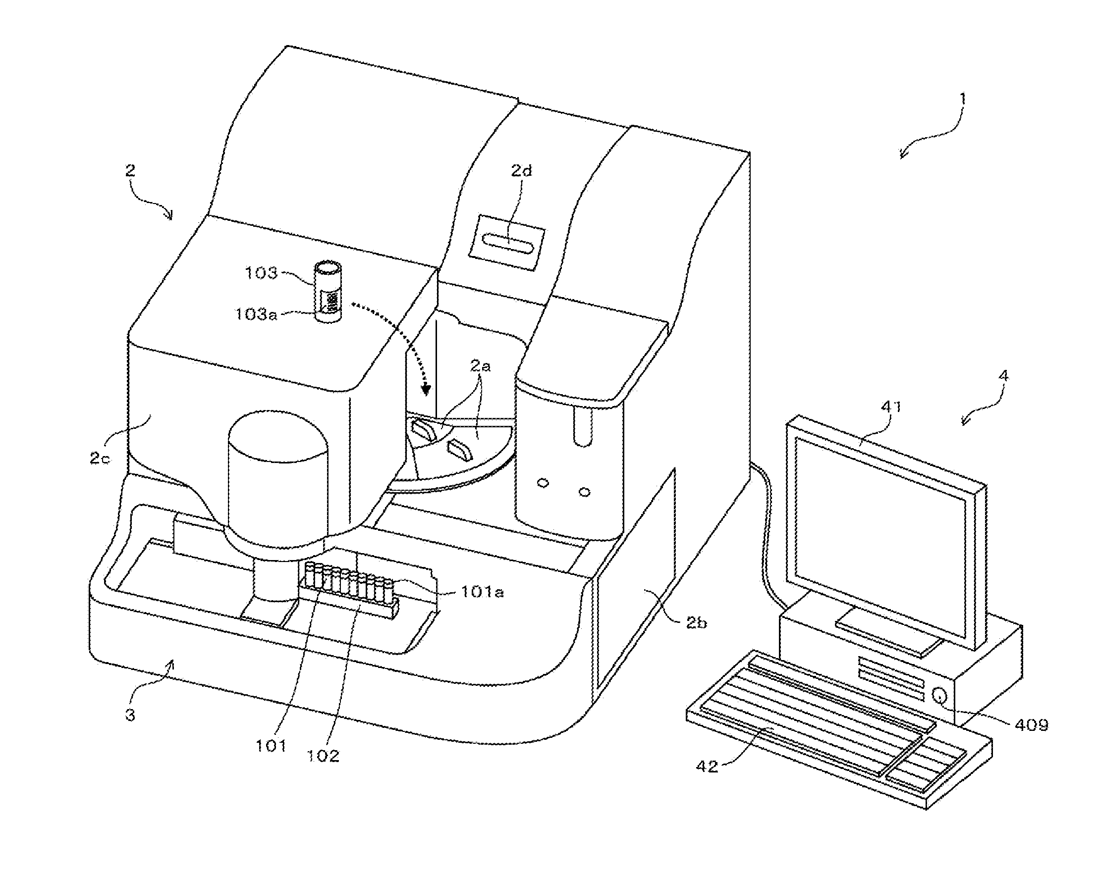
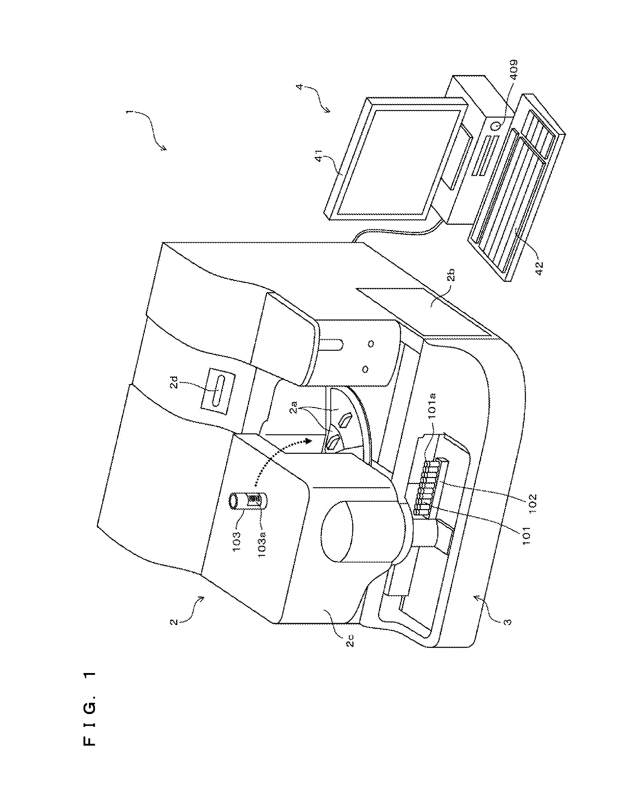
[0048]FIG. 1 is a perspective view showing an external structure of a blood coagulation analyzer 1.
[0049]The blood coagulation analyzer 1 includes a measurement unit 2 which optically measures components contained in a sample (plasma), a sample transporter 3 arranged to the front of the measurement unit 2, and a control device 4 which analyzes measurement data obtained by the measurement unit 2 and which provides instructions to the measurement unit 2.
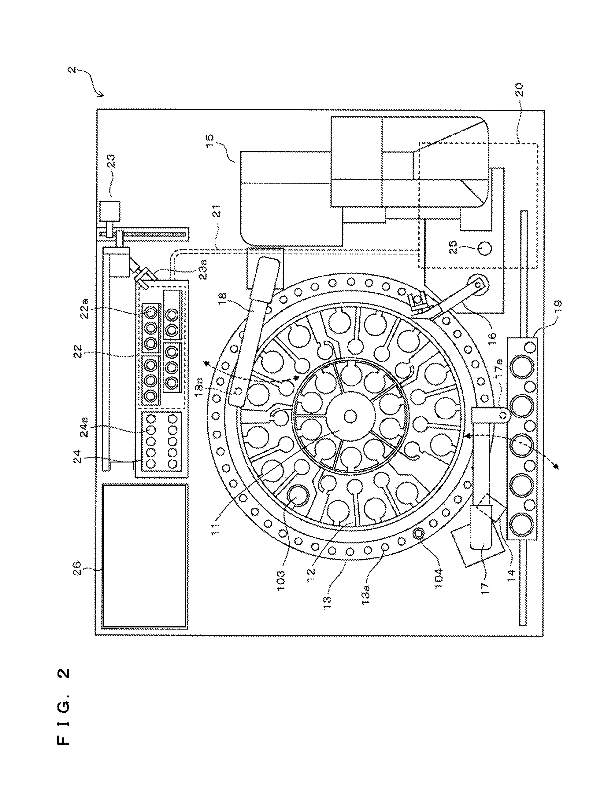
[0050]The measurement unit 2 is provided with lids 2a and 2b, a cover 2c, and a power button 2d. A user can open the lid 2a to replace reagent containers 103 set in reagent tables 11 and 12 (see FIG. 2) with new reagent containers 103, and to newly add other reagent containers 103 thereto. Each reagent container 103 has attached thereto a bar code label 103a on which a bar code is printed, the bar code including the type of a reagent contained therein and a reagent ID composed of a serial number given to the reagent.
[0051]Further, the ...
second embodiment
[0133]In the first embodiment above, when it has been determined that blood coagulation reaction had not occurred during the measurement time period T1, the measurement result is masked on the screen shown in FIG. 9. In the present embodiment, when it has been determined that blood coagulation reaction had not occurred during the measurement time period T1, information indicating necessity / unnecessity of re-measurement is further received. When the user has inputted an instruction to perform re-measurement, the blood coagulation analyzer 1 performs measurement again on the sample for which it has been determined that blood coagulation reaction had not occurred, and calculates a prothrombin time (PT). Here, a measurement time period T2 in the re-measurement is set to be longer than the measurement time period T1 in the measurement of the first time (for example, T2=2×T1).
[0134]In the present embodiment, in order to allow re-measurement, the sample is dispensed from a sample container...
third embodiment
[0147]In the second embodiment, when it has been determined that blood coagulation reaction had not occurred, re-measurement is performed after waiting for receiving an instruction from the user. In contrast, in the present embodiment, when it has been determined that blood coagulation reaction had not occurred, re-measurement is automatically performed.
[0148]FIG. 14 is a flow chart showing a measurement process of a prothrombin time (PT) in the present embodiment. In steps S11 to S16 and steps S21 and S22 in FIG. 14, the same processes as those in the corresponding steps in FIG. 12 are performed.
[0149]Upon receiving measurement results of the first time from the measurement unit 2 (S21), the control device 4 performs the analysis process shown in FIG. 8B (S22). Subsequently, the control device 4 determines whether re-measurement has already been performed (S41). When re-measurement has not been performed (S41: NO), the control device 4 determines whether the flag has been given in ...
PUM
| Property | Measurement | Unit |
|---|---|---|
| second wavelength | aaaaa | aaaaa |
| second wavelength | aaaaa | aaaaa |
| center wavelengths | aaaaa | aaaaa |
Abstract
Description
Claims
Application Information
 - Generate Ideas
- Intellectual Property
- Life Sciences
- Materials
- Tech Scout
- Unparalleled Data Quality
- Higher Quality Content
- 60% Fewer Hallucinations
Browse by: Latest US Patents, China's latest patents, Technical Efficacy Thesaurus, Application Domain, Technology Topic, Popular Technical Reports.
© 2025 PatSnap. All rights reserved.Legal|Privacy policy|Modern Slavery Act Transparency Statement|Sitemap|About US| Contact US: help@patsnap.com