
Vertically Retractable Shelving for Home or Office

Active Publication Date: 2014-09-11
REID WAYNE HYWARD +1
View PDF17 Cites 24 Cited by
  • Summary
  • Abstract
  • Description
  • Claims
  • Application Information

AI Technical Summary

Benefits of technology

The patent describes a retractable, motorized shelving system that can safely operate in an occupied space and is aesthetically pleasing. The system has various advantages such as allowing for both aesthetic and functional variations in shelving, being simple to install in typical structures and being able to accommodate unusual conditions and circumstances. The shelving system can be installed in a framed drop ceiling or in a framed cabinet which extends below the normal ceiling level. The shelf can be operated by means of a wall switch, keyed wall switch, remote control, smart phone, computer, computer via the internet, incorporated into a smart home system, or by a manual override. The shelving system can be equipped with sensors to stop operation due to obstruction or forces that could adversely affect normal operation. The system has adequate stability to allow for operation or being used as a shelf in the lowered position in occupied spaces. The lower shelf has a large amount of flexibility in construction, size, number, position, materials, and uses. The system can be used as a shelf、closet、rack for hanging items、or platform lift. The closures are fixed to the shelving system and do not require any additional moving parts. The system can accommodate relatively high lifting capacities or shelf loads. It can be operated by various means such as wall switch, keyed wall switch, remote control, smart phone, computer, computer via the internet, or manual override. The system can be equipped with sensors to stop operation due to obstruction or forces that could adversely affect normal operation.

Problems solved by technology

Such access is generally for maintenance and is not intended for storage access.
Systems similar to that of a dumb waiter may be less than ideal for everyday use.
These systems are utilitarian in nature and are not suitable for use in livable or office space.
These cable supported platforms do not, by their nature, have lateral or torsional stability in the horizontal plane other than that provided by the restoring force due to the displaced angle of the cables.
This can lead to the platform moving like a pendulum and twisting about a vertical axis.
This movement poses problems when used in livable or office space and could result in damage to items around the shelf as well as contents of the shelf, and pose a hazard for persons near the shelf.
A further disadvantage is that care must be taken to ensure the shelf is stable when being raised or lowered and is lined up with the hole in the ceiling into which the platform must enter.
Further, the ability to increase the height of the lift above the ceiling level is restricted because it increases the free length of the telescoping tubes, making them even more flexible.
Although, the tubes can provide some stability compared to other cable systems, due to their unsupported length when in the lowered position, and the method of attachment to the structure above, the amount of lateral stability provided is questionable.
The indicated connections to the structure are not adequate to reliably fix the tubes and could significantly degrade with use.
In addition, the weight of the platform is carried by the cables inside the tubes, thus the tubes do not benefit from increased stiffness which would result from tension in the tubes.
In addition to the disadvantages described above, platform lifts generally suffer from at least one or more of the following disadvantages: (a) Utilitarian in design, limited attempt to address aesthetics for use in livable or office space; (b) Questionable lateral stability, which is important for storage of some items and may be a safety and operational concern in occupied areas; (c) Only receives support from the upper floor or ceiling structure.
Although in some cases supporting structures can be addressed during installation, there are no provisions accounted for in the systems to aid in this regard.
The guides do not appear to provide much stability, but are used to guide the closet into the upper compartment.
The cabinet does not provide for a ceiling closure when either in the lowered or raised position.
The space in the attic which houses the closet in the raised position can isolate the contents form the rest of the attic space, but it is noted that in Spencer the motor is outside the box and drive chains penetrate the box, resulting in a problem with sealing the enclosure from the unconditioned attic space.
Further, no mechanism is provided to lower the closet in the event of a power or equipment failure.
The telescoping, however, is the closet itself, so the top of the shelf cannot be lower than the ceiling.
Therefore the height of the shelving is limited, to a much greater extent than the telescoping systems, to the available height in the attic.
Closet lift type systems generally suffer from at least the following disadvantages: (a) Utilitarian in design; (b) When in the lowered position, do not provide a ceiling closure; (c) When in the lowered position, the cables and guides are visible and unsightly; (d) Closets that extend to the ceiling when in the lowered position, require a tall closet and therefore a tall attic space in order to be accessible near floor or table height; (e) Maintenance of the lifting mechanism (motor, pulleys, springs, guides, etc.) will typically require access from the attic and partial removal of the housing in the attic; (f) As depicted in the patents, the closet systems address relatively light loads.
Methods for increasing the capacity of the supporting framing are not addressed; (g) In addition, many of the disadvantages given for platform lifts apply.

Method used


Image

  • Vertically Retractable Shelving for Home or Office
  • Vertically Retractable Shelving for Home or Office
  • Vertically Retractable Shelving for Home or Office

Examples


Embodiment Construction

[0137]The one example embodiment will be described with reference to the accompanying figures. It is to be understood that the specific apparatus and system illustrated in the figures and specification is simply and exemplary embodiment of the invention.

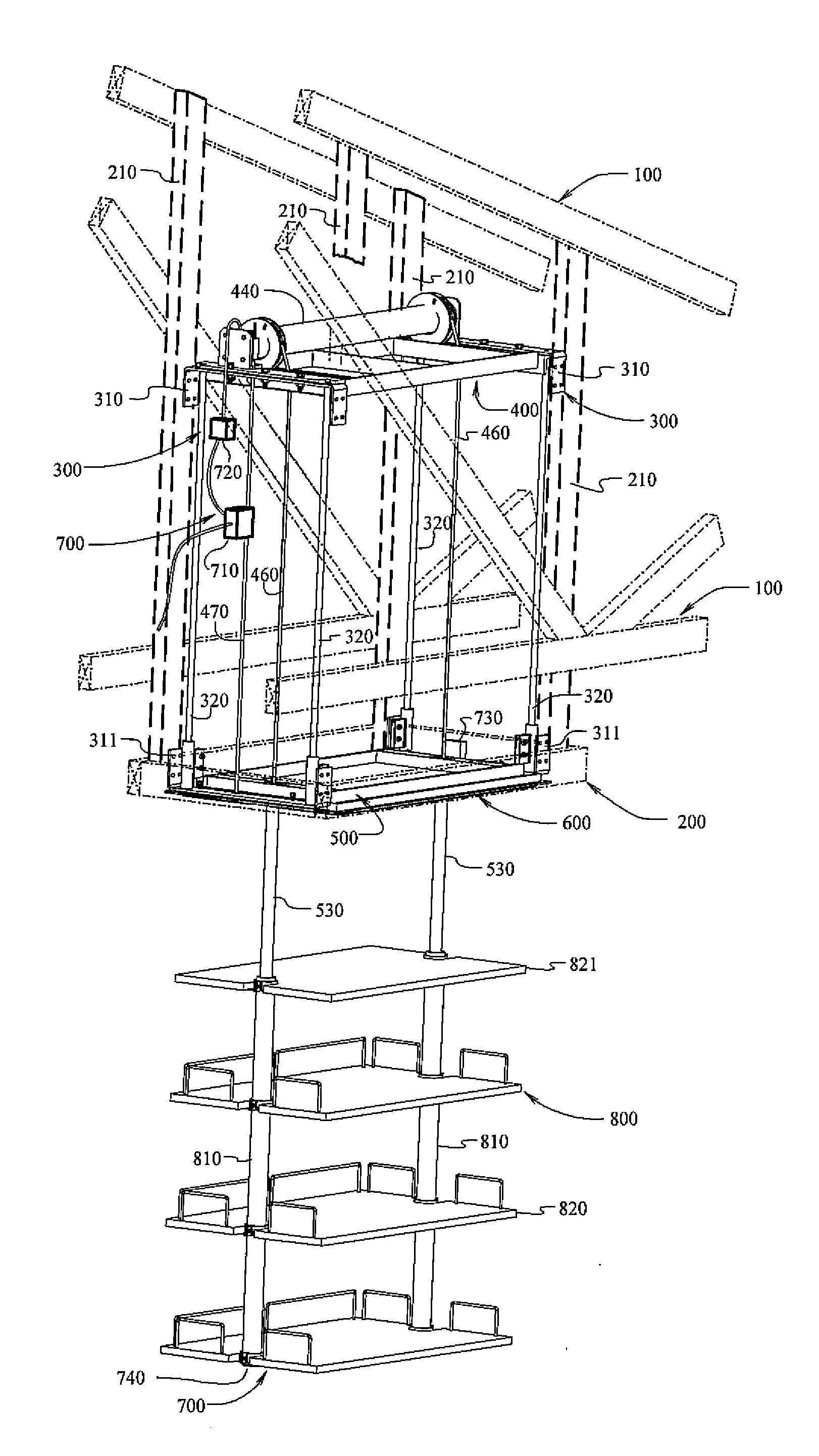
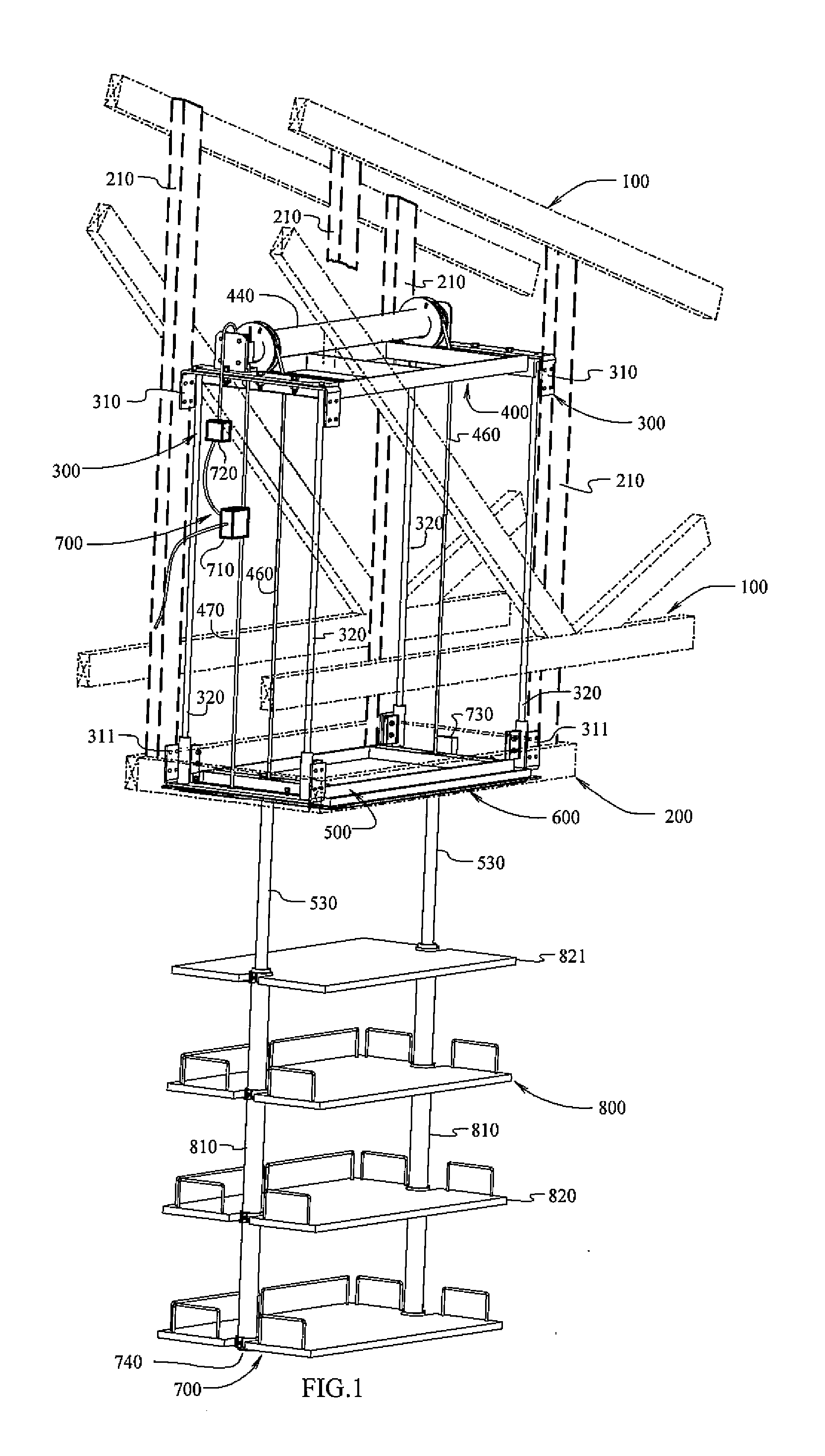
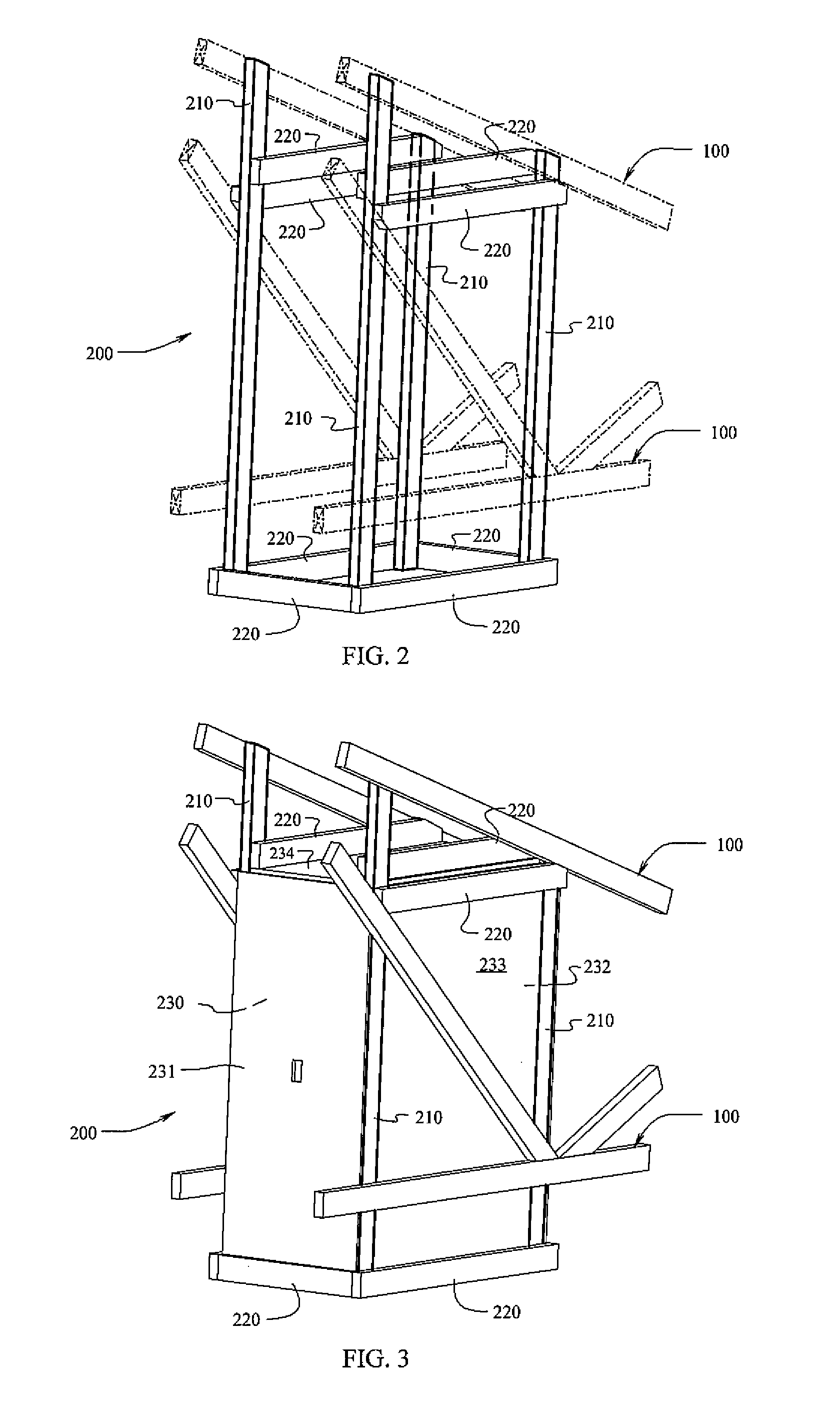
[0138]A retractable shelving system installed in the attic space between roof trusses is shown in FIG. 1. In one example, the system includes a lower shelf (800), a floating frame (500), vertical guide frames (300), a top frame (400), a motor (440), a sensor frame (600) and electronic operation including remote control and sensors (700). Further, the system may include a cabinet (200) for housing the system in, for example, an attic.

[0139]Generally, the parts may be made of metal, such as aluminum, steel, stainless steel, plastic, or of sturdy materials. These structural components are preferably of a unitary construction, except as noted, to provide strength and rigidity. Such components may be molded, extruded or machined into the ...


PUM


Abstract

A retractable shelving system is described. In one example, the retractable shelving system includes a lower shelf, a floating frame, vertical guide frames, a top frame, a motor, a sensor frame and electronic operation including remote control and sensors. In another example a cabinet is included for housing the shelving system in the attic.

Description

CROSS-REFERENCE TO RELATED APPLICATIONS[0001]This application claims the benefit of U.S. Provisional Application No. 61 / 772,715, filed Mar. 5, 2013, which is hereby incorporated by reference in its entirety.STATEMENT REGARDING FEDERALLY SPONSORED RESEARCH OR DEVELOPMENT[0002]Not Applicable.FIELD OF THE INVENTION[0003]The present invention relates to retractable storage systems, and more specifically to storage systems and shelving systems that retract up into an overhead space.BACKGROUND OF THE INVENTION[0004]The following is a tabulation of some U.S Patents and U.S. Patent Application Publications that presently appears relevant:U. S. PatentsPatent NumberKind CodeIssue DatePatentee2,499,791B11950 Mar. 9Spencer4,412,601B11983 Nov. 1Cooper5,203,619B11993 Apr. 20Welsch et al5,475,949B11995 Dec. 19McCoy5,535,852B11996 Jan. 16Bishop et al.5,667,035B11997 Sep. 16Hughes6,131,702B12000 Aug. 17Berridge6,250,728B12001 Jun. 26Thorp6,779,634B12004 Aug. 24Slagle7,575,098B22009 Aug. 18Hartley7,9...

Claims


Application Information

Patent Timeline
IPC IPC(8): A47B46/00
CPCA47B46/005A47B51/00A47B2051/005E04F19/08
Inventor REID, WAYNE HYWARDREID, QUINN THOMAS
Owner REID WAYNE HYWARD
Learn More