
Control device for internal combustion engine

Inactive Publication Date: 2014-09-11
TOYOTA JIDOSHA KK
View PDF0 Cites 1 Cited by
  • Summary
  • Abstract
  • Description
  • Claims
  • Application Information

AI Technical Summary

Benefits of technology

The device described in this patent controls the opening of a passage space to decrease pumping loss and increase fuel efficiency in an engine. This is done by controlling the area of the opening of the passage space to match the supercharging pressure with a predetermined target, while preventing the consumption of fuel that does not contribute to the torque of the engine.

Problems solved by technology

Furthermore, the amount of air guided to the combustion chamber increases with increasing amount of the supercharging pressure, and then the amount of fuel to be combusted in the combustion chamber increases.
The amount of work through a combustion cycle of the engine then increases with increasing amount of fuel to be combusted.
Furthermore, the loss of the amount of work generated by the engine (the negative amount of work in the exhaust stroke and the intake stroke: So-called pumping loss) increases with increasing amount of the exhaust pressure.
That is, the pumping loss increases with decreasing amount of the area of the opening of the passage space, and the pumping loss decreases with increasing amount of the area of the opening of the passage space.

Method used


Image

  • Control device for internal combustion engine
  • Control device for internal combustion engine
  • Control device for internal combustion engine

Examples


first embodiment

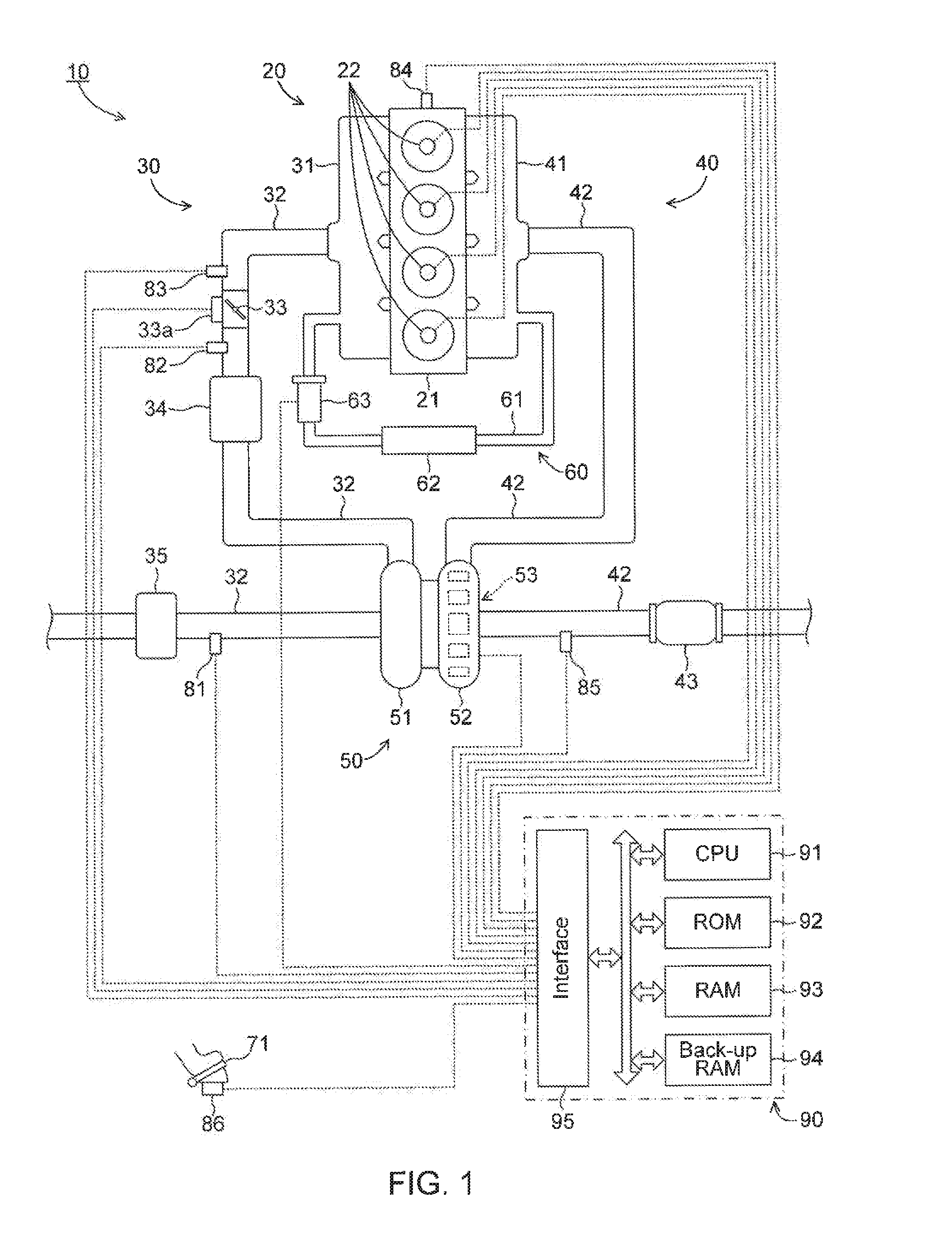
[0047]FIG. 1 illustrates a schematic configuration of a system in which the control device according to the first embodiment of the present invention (hereinafter referred to as “first device”) is applied to an internal combustion engine 10. The internal combustion engine 10 is a four-cycle diesel engine. The internal combustion engine 10 is hereinafter simply referred to as “engine 10” for the sake of convenience.

[0048]As illustrated in FIG. 1, the engine 10 includes a main body 20 including a fuel injection system, an intake system 30 to guide air into the main body 20, an exhaust system 40 to discharge gas from the main body 20 to outside of the engine 10, a supercharger 50 driven by using energy of exhaust gas to compress air guided to the main body 20, and an EGR unit 60 to recirculate exhaust gas from the exhaust system 40 to the intake system 30.

[0049]The main body 20 includes a cylinder head 21 through which the intake system 30 and the exhaust system 40 are connected. The c...

second embodiment

[0077]The following is an embodiment in which “a target value of the degree of change in the area of the opening of the passage space is determined based on the sum of the first degree of change in torque and the second degree of change in torque, and the target value of the fuel supply amount is determined based on the target value of the area of the opening of the passage space” as one embodiment of the first device.

[0078]The control device according to this embodiment (hereinafter referred to as “second device”) is applied to an engine that has the same configuration as that of the first device (see FIG. 1, and hereinafter referred to as “engine 10” for convenience).

[0079]The second device employs, as the first degree of change in torque, the rate of the amount of torque after changing the area of the opening of the passage space with respect to the amount of torque before changing the area of the opening of the passage space (that is, the change rate of torque: hereinafter refer...


PUM


Abstract

A control device of the invention is applied to an engine including a supercharger and a mechanism to allow area of an opening of a passage space to be variable, which space is to pass through exhaust gas guided to the supercharger. The control device changes the above area and a fuel supply amount to a combustion chamber based on a first degree of change in torque and a second degree of change in torque. The first degree is due to a change in an intake air amount to the combustion chamber to be occurred along with the change in the above area, and the second degree is due to a change in pressure of the exhaust gas to be occurred along with the change in the above area.

Description

TECHNICAL FIELD[0001]This invention relates to a control device that includes a supercharger.BACKGROUND ART[0002]Internal combustion engines with supercharger (so-called variable geometry Supercharger, VGT) are conventionally designed, and such supercharger includes a turbine to which exhaust gas is guided and a compressor with which air is compressed when being coordinated with the turbine to enable an adjustment of supercharging characteristic by controlling an area of an opening of a space through which exhaust gas is guided to the turbine.[0003]One of conventional control device applied to this kind of internal combustion engine (hereinafter referred to as “conventional device”) is designed to control the pressure of air (supercharging pressure) guided to combustion chambers of the engine by controlling the pass space of the space depending on the situation such as operating condition of the engine (for example, see the patent literature 1). The space through which exhaust gas i...

Claims


Application Information

Patent Timeline
IPC IPC(8): F02D23/02F02B37/22
CPCF02B37/22F02D23/02F02B37/24F02D41/0007F02D2200/1004F02D2250/18F02D41/10F02D41/1448F02D41/18F02D2250/34Y02T10/12
Inventor IBUKI, TAKU
Owner TOYOTA JIDOSHA KK
Learn More