
Inter-layer prediction between layers of different dynamic sample value range

a dynamic sample value and inter-layer prediction technology, applied in the field of inter-layer prediction, can solve the problems of low efficiency of this predictor, limited ilp parameter estimation ability, inefficient code of useful side information, etc., and achieve the effect of suppressing global prediction, avoiding transmission overhead, and efficiently code slope and intercep

Active Publication Date: 2014-08-28
FRAUNHOFER GESELLSCHAFT ZUR FOERDERUNG DER ANGEWANDTEN FORSCHUNG EV
View PDF2 Cites 62 Cited by
  • Summary
  • Abstract
  • Description
  • Claims
  • Application Information

AI Technical Summary

Benefits of technology

The patent describes an apparatus for predicting video content between two stages of coding. The apparatus uses a global predictor to analyze video content and create a global predicted reference picture for the second stage of coding. The apparatus also uses a local predictor to create a globally and locally predicted reference picture for the second stage of coding by analyzing video content in smaller parts of the picture. The global predictor uses regression analysis to determine the expected values of co-located samples in the video content. The local predictor uses a straight line fit and interpolation to create a prediction residual based on the global and local predicted reference pictures. The apparatus improves video quality and reduces the amount of data needed to store the video content.

Problems solved by technology

However, the efficiency of this predictor is low whenever the LDR video was generated by a locally adaptive TMO (which usually produces more attractive LDR videos).
The approaches in [3-6] exhibit some local adaptivity, by using a block-wise ILP, however they are operating in a color space that is not suited for transmitting HDR data.
Furthermore, they have only limited capabilities for ILP parameter estimation and the useful side information is inefficiently coded.

Method used


Image

  • Inter-layer prediction between layers of different dynamic sample value range
  • Inter-layer prediction between layers of different dynamic sample value range
  • Inter-layer prediction between layers of different dynamic sample value range

Examples


Embodiment Construction

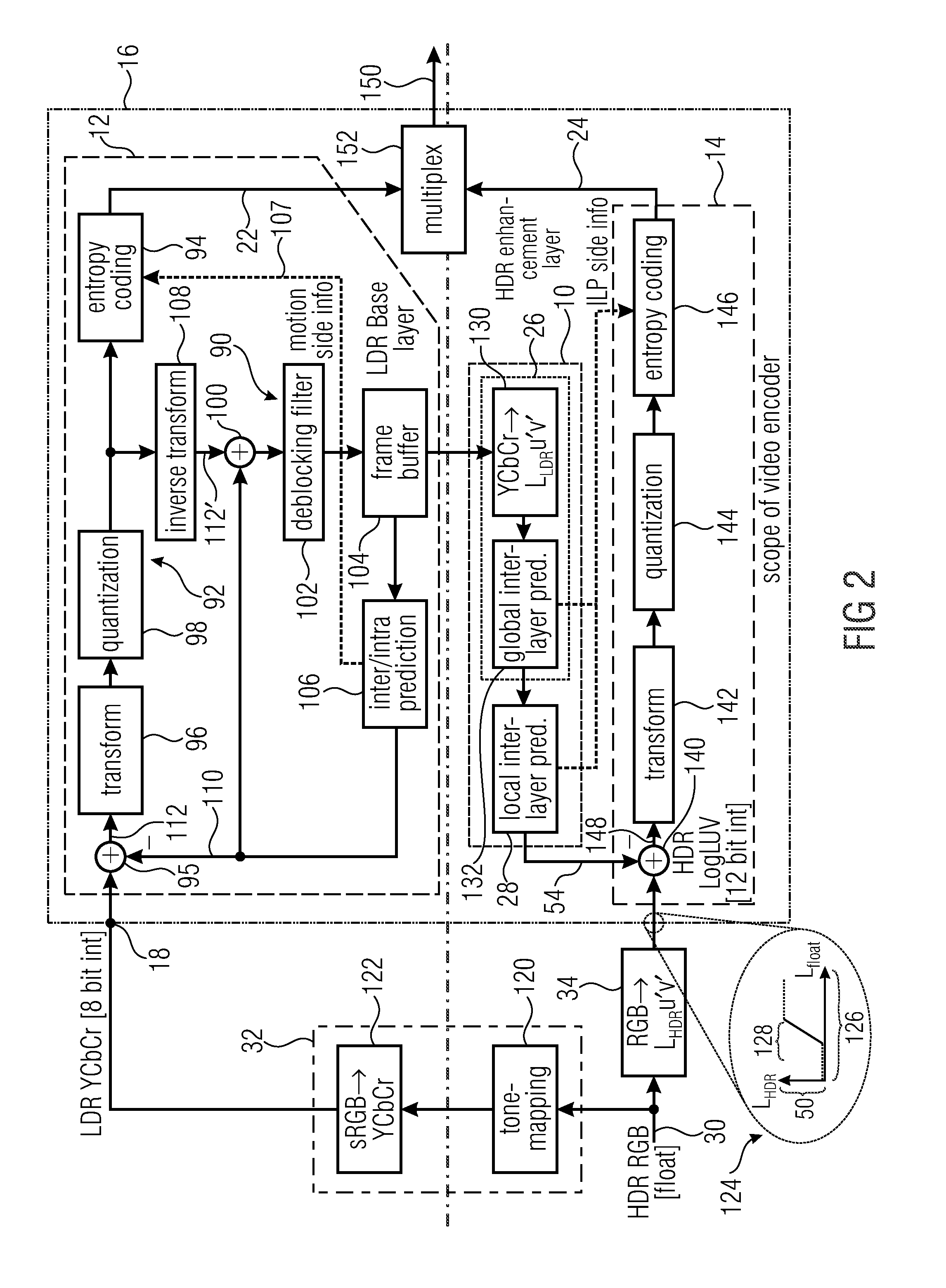
[0022]FIG. 1 shows an embodiment of an apparatus 10 for performing inter-layer prediction between a first picture coding stage 12 for coding a first tone-mapped version of a picture, and a second picture coding stage 14 for coding a second version of the picture. The first tone-mapped version of the picture coded by the first picture coding stage 12 has a first dynamic sample value range. For example, the first picture coding stage 12 operates at integer sample values of bit length m. The second version of the picture coded by the second picture coding stage 14 has a second dynamic sample value range which is greater than the first dynamic sample value range. For example, the second picture coding stage 14 may be configured to operate at integer sample values of bit length n with n>m. In the more detailed embodiment of FIG. 2, n is 12 and m is 8.

[0023]FIG. 1 shows the apparatus 10 for performing inter-layer prediction, the first picture coding stage 12 and the second picture coding ...


PUM


Abstract

The ratio between coding quality on the one hand and coding rate on the other hand is increased. To this end, a global predictor and a local predictor are used in combination. The global predictor derives a global tone-mapping function based on a statistical analysis of pairs of values of co-located samples in the first tone-mapped version and the second version of the picture, and applies the global tone-mapping function onto the first tone-mapped version of the picture. The local predictor locally derives a locally varying tone-mapping function based on a statistical analysis of values of co-located samples in the second version of the picture and the globally predicted reference picture in units of sub-portions into which the globally predicted reference picture and the second version of the picture are partitioned, and applies the locally varying tone-mapping function onto the globally predicted reference picture.

Description

CROSS-REFERENCE TO RELATED APPLICATIONS[0001]This application is a continuation of copending International Application No. PCT / EP2012 / 058227, filed May 4, 2012, which is incorporated herein by reference in its entirety, and additionally claims priority from U.S. Application No. 61 / 557,675, filed Nov. 9, 2011, which is also incorporated herein by reference in its entirety.[0002]The present invention is concerned with inter-layer prediction between layers of different dynamic sample value range in picture and / or video coding.BACKGROUND OF THE INVENTION[0003]The human visual system can perceive luminance ranges of about 8 orders of magnitude and about 5 orders simultaneously when adapted to a certain light condition [1]. In contrast, until a few years ago, the dynamic range of most video capture and display devices was limited to about two orders of magnitude. Today, with the introduction of commercial HDR displays, a dramatically increased realism can be expected when the full visible...

Claims


Application Information

Patent Timeline
IPC IPC(8): H04N19/11H04N19/17H04N19/196H04N19/167
CPCH04N19/00042H04N19/00248H04N19/0026H04N19/00369H04N19/11H04N19/14H04N19/147H04N19/167H04N19/17H04N19/172H04N19/176H04N19/196H04N19/39H04N19/46H04N19/463H04N19/98
Inventor GARBAS, JENS-UWETHOMA, HERBERT
Owner FRAUNHOFER GESELLSCHAFT ZUR FOERDERUNG DER ANGEWANDTEN FORSCHUNG EV
Learn More