
Device for manufacturing components from fiber-reinforced composites

a technology of fiber reinforced composites and manufacturing components, which is applied in the direction of manufacturing tools, auxillary shaping apparatus, ceramic shaping apparatus, etc., can solve the problems of increased weight, poor mechanical properties of finished components, and high underpressure first generated in the mold chamber

Inactive Publication Date: 2014-08-21
FASERVERBUND INNOVATIONS UG HAFTUNGSBESCHRANKT
View PDF1 Cites 4 Cited by
  • Summary
  • Abstract
  • Description
  • Claims
  • Application Information

AI Technical Summary

Benefits of technology

The present invention aims to provide a device that limits the inflow of matrix materials accurately and reliably to the desired fiber volume content. This is achieved by using a ball seat valve that acts as a sensor, closure element, and actuator, which interrupts the inflow of matrix material when the pressure differential between the ambient pressure and the underpressure in the inflow connector reaches a certain threshold. This prevents more matrix material from flowing into the mold chamber than required, reducing the weight and worsened mechanical properties of the finished component. The spring force-actuated ball seat valve is a safe, precise, and economical solution that achieves a high repetition precision and uniform product quality.

Problems solved by technology

In the normal uncontrolled working process of the device, a high underpressure is first generated in the mold chamber by removing the gas contained in the mold chamber by suction via the suction connector with a vacuum pump.
This applies even when in the suction connector a vacuum or underpressure is still existing because the matrix material cannot overcome the blocking membrane to the gas suction passage.
When the inflow of matrix material into the mold chamber is not interrupted before a force equilibrium relative to the ambient pressure is produced, more matrix material flows into the mold chamber then is required for actual embedding of the same fiber quantity in the matrix material; this causes an increased weight and worsened mechanical properties of the finished component.

Method used


Image

  • Device for manufacturing components from fiber-reinforced composites
  • Device for manufacturing components from fiber-reinforced composites

Examples


Embodiment Construction

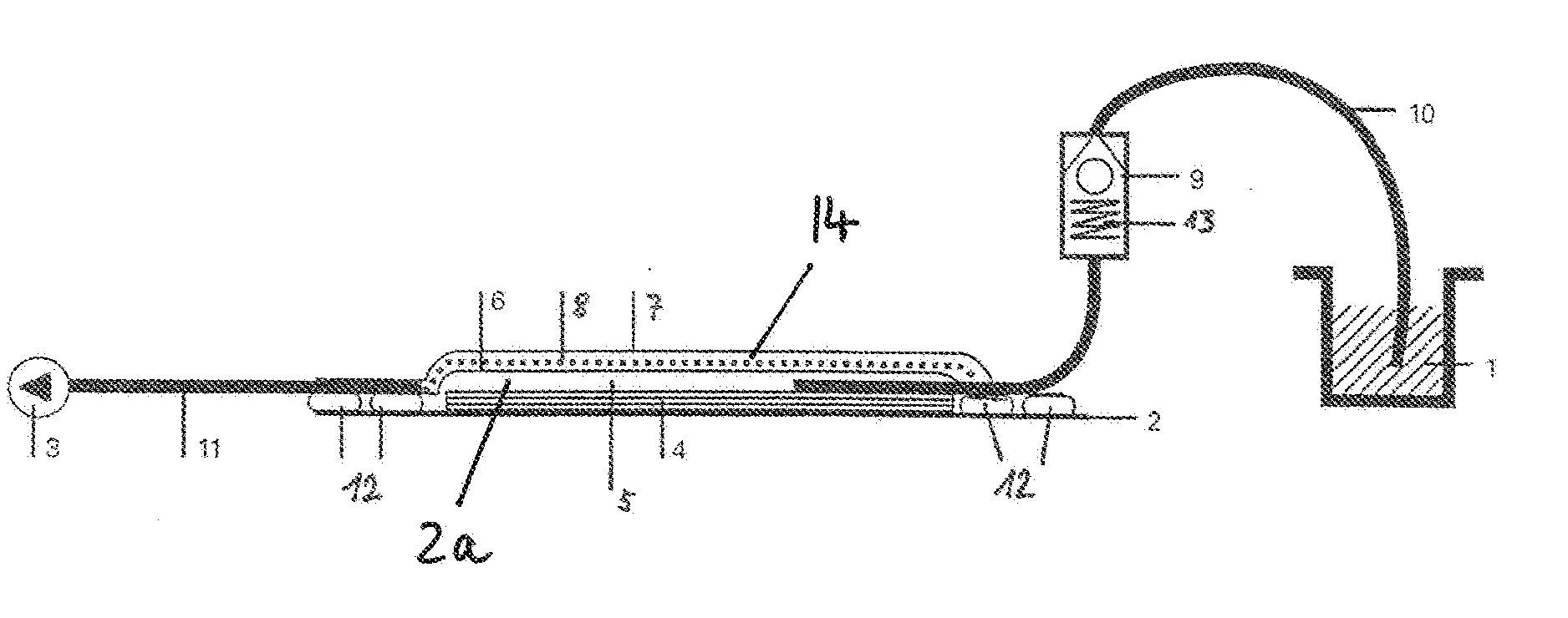
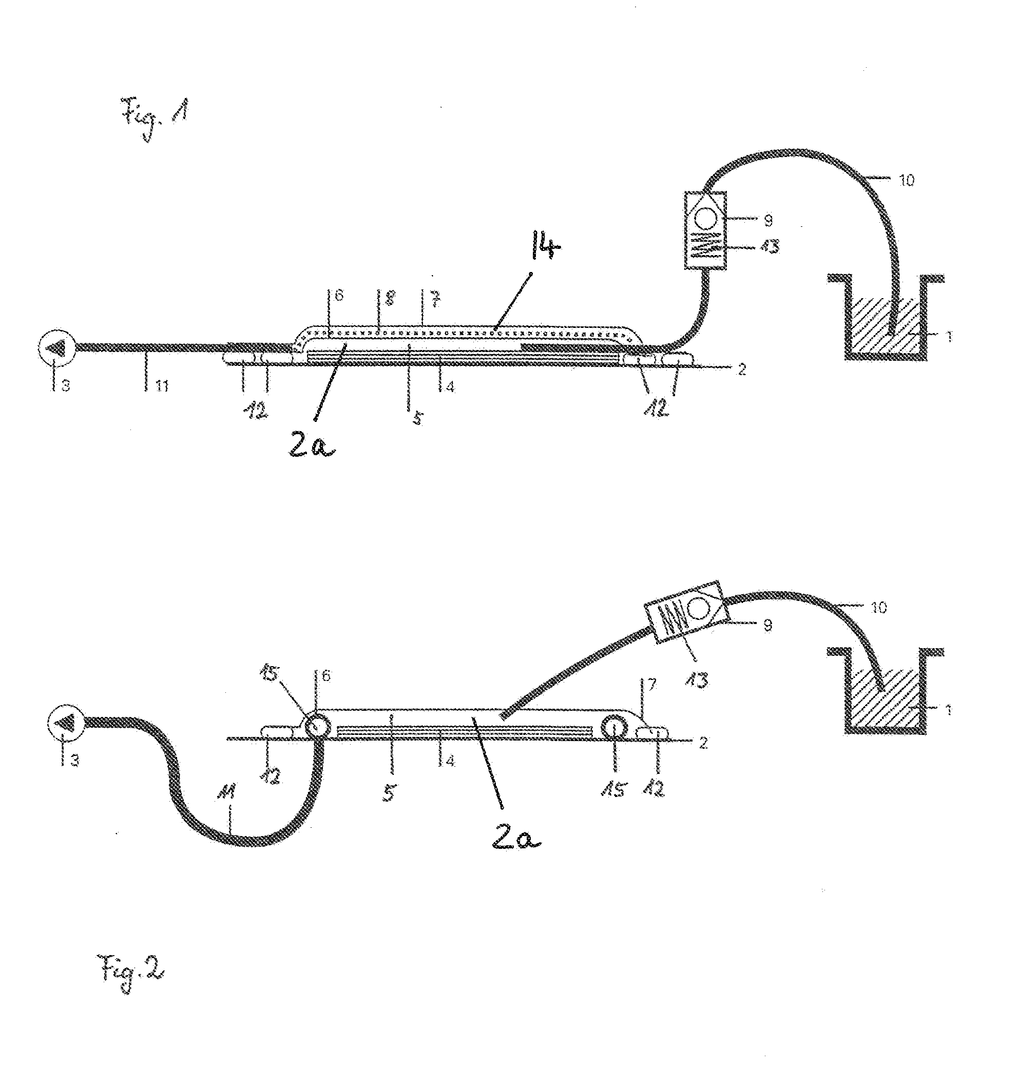
[0020]FIG. 1 discloses a device according to the invention in which a matrix material flows into the mold 2 from the resin container 1. The matrix material is sucked by means of a vacuum pump 3 from the resin container 1 into the mold chamber 2a into which, prior to this, fiber material 4 has been placed that is then impregnated with the matrix material 5 which is pumped from the resin container 1. In the illustration of FIG. 1, the fiber material 4 and the matrix material 5 are illustrated in a simplified form as two layered materials. In reality, the matrix material 5 penetrates into the fiber material 4 so that a fiber-reinforced composite component is produced therefrom in the mold 2.

[0021]The mold chamber 2a is sealed relative to gas that is exterior to the mold 2 by an airtight cover film 7, i.e., is sealed in particular relative to air. At the edges of the mold 2 the cover film 7 in the illustrated embodiment is additionally sealed by one or several seal strips 12.

[0022]In or...


PUM

PropertyMeasurementUnit
Pressureaaaaaaaaaa
Pressureaaaaaaaaaa
Pressureaaaaaaaaaa

Abstract

A device for producing fiber-reinforced composites has a mold with an airtightly closed mold chamber for forming a composite of fiber material and matrix material. A membrane in the mold separates fiber and matrix material from a gas suction passage. A suction connector is connected to the mold and sucks gas out of the mold chamber via the gas suction passage. The matrix material flows from the resin container into the mold chamber through an inflow connector. A sensor provided on the inflow connector or the resin connector and connected to the actuator measures actual pressure existing in the inflow connector or the resin connector. An actuator is connected to the closure element and moves the closure element, when activated by a trigger signal emitted by the sensor, from an open into a closed position so that the closure element closes off the inflow connector or the resin container.

Description

BACKGROUND OF THE INVENTION[0001]The invention relates to a device for manufacturing components from fiber-reinforced composites. The device comprises a mold that comprises an air-tightly closeable mold chamber for receiving and forming a composite of a fiber material and a matrix material. Into the mold, a membrane element for separating the fiber material and the matrix material from a gas suction passage can be inserted. The device further comprises a suction connector for removing by suction the gas that is contained in the mold chamber, wherein the suction connector is connected with the mold by means of the gas suction passage. The device further comprises an inflow connector for a matrix material that is to be introduced from a resin container into the mold chamber.[0002]A device of the aforementioned kind is disclosed, for example, in U.S. Pat. No. 6,843,953. A device and a method are described wherein, by applying a vacuum to a mold, a matrix material is sucked from a resin...

Claims


Application Information

Patent Timeline
IPC IPC(8): B29C70/54B29C33/00
CPCB29C33/00B29C70/546B29C70/443
Inventor DIERKES, DOMINIK
Owner FASERVERBUND INNOVATIONS UG HAFTUNGSBESCHRANKT
Learn More