
Sound input device

a sound input and input technology, applied in the direction of loudspeakers, microphone structural associations, semiconductor electrostatic transducers, etc., can solve the problems of difficult to make a plurality of sound guide spaces, and first, to ensure good noise suppression performance, etc., to achieve the effect of good noise suppression

Inactive Publication Date: 2014-08-21
FUNAI ELECTRIC CO LTD
View PDF2 Cites 27 Cited by
  • Summary
  • Abstract
  • Description
  • Claims
  • Application Information

AI Technical Summary

Benefits of technology

The patent text describes a differential microphone that can effectively suppress background noise and is highly sensitive to sound. The technical effect of this invention is to provide a sound input device with proper sensitivity and noise suppression.

Problems solved by technology

For instance, it has been discovered that if a differential microphone is configured so as to take into account the need for reducing size and thickness, it is difficult to make a plurality of sound guide spaces (e.g., first and second sound guide spaces) the same as in Patent Literature 1.
As a result, it is difficult to ensure good noise suppression performance, for example.

Method used


Image

  • Sound input device
  • Sound input device
  • Sound input device

Examples


Embodiment Construction

[0027]A selected embodiment will now be explained with reference to the drawings. It will be apparent to those skilled in the art from this disclosure that the following descriptions of the embodiment are provided for illustration only and not for the purpose of limiting the invention as defined by the appended claims and their equivalents.

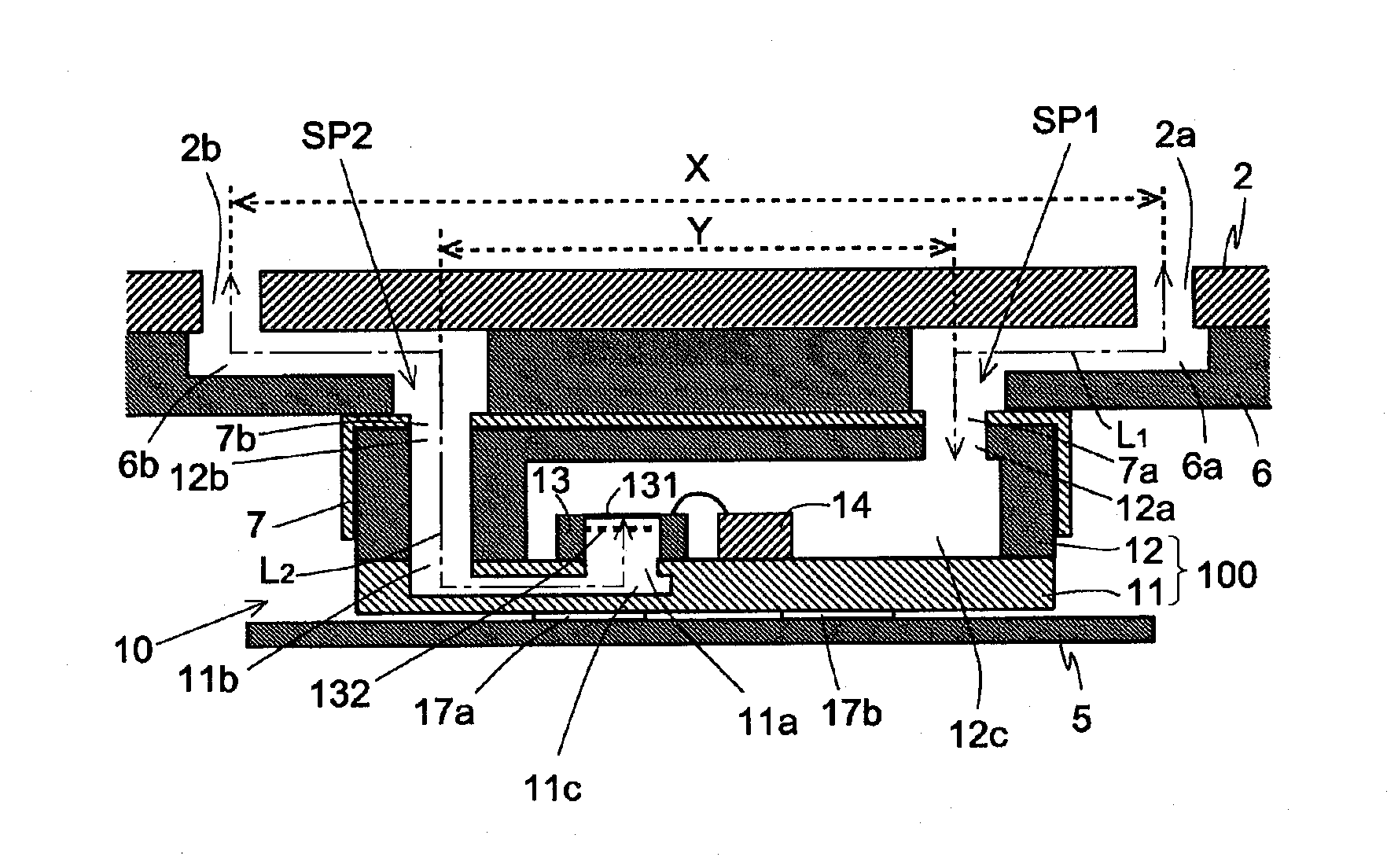
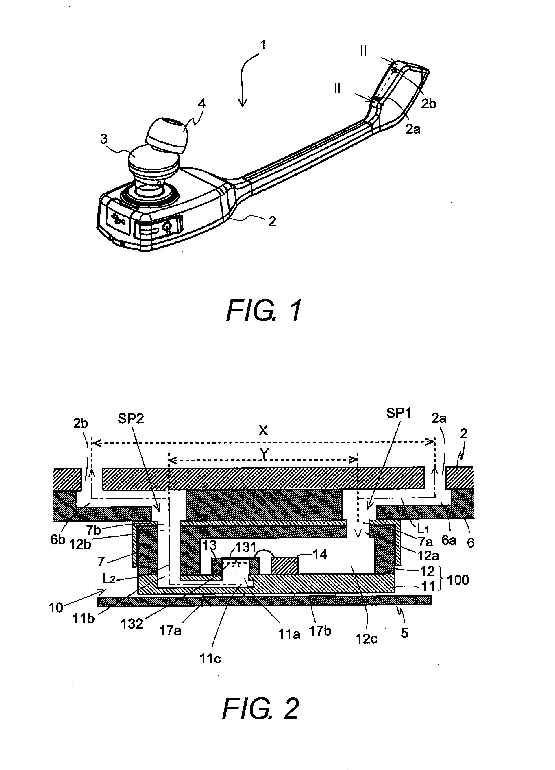
[0028]Referring initially to FIGS. 1 to 12, a headset 1 (e.g., a sound input device) is illustrated in accordance with one embodiment. In the illustrated embodiment, the head set 1 is an example of the sound input device of the present invention. In the illustrated embodiment, while the headset 1 is illustrated as an example of the sound input device, it will be apparent to those skilled in the art from this disclosure that the present invention can be applied to different types of sound input device, such as portable telephones and other such voice communication devices, information processing systems that make use of technology for analyzing inp...


PUM


Abstract

A sound input device includes a housing, a microphone housing, a vibrator, and first and second sound guide components. The housing has first and second sound collection holes. The microphone housing has first and second microphone sound holes. The first and second sound guide components communicate with the first and second sound collection holes and the first and second microphone sound holes, respectively. The microphone housing has a first microphone inner space that communicates with the first microphone sound hole and one side of the diaphragm of the vibrator, and a second microphone inner space that communicates with the second microphone sound hole and the other side of the diaphragm. A spacing between the first sound collection hole and the second sound collection hole is wider than a spacing between the first microphone sound hole and the second microphone sound hole.

Description

CROSS-REFERENCE TO RELATED APPLICATIONS[0001]This application claims priority to Japanese Patent Application No. 2013-027451 filed on Feb. 15, 2013. The entire disclosure of Japanese Patent Application No. 2013-027451 is hereby incorporated herein by reference.BACKGROUND[0002]1. Field of the Invention[0003]This invention generally relates to a sound input device.[0004]2. Background Information[0005]Generally, sound input devices with which sound input is possible and which execute signal processing related to inputted sound are well-known in the art. For example, sound input devices have been applied to portable telephones, headsets, and other such speech communication devices, information processing systems that make use of technology for analyzing inputted sound (such as voice authentication systems, voice recognition systems, command generation systems, electronic dictionaries, translators, and voice-input remote controls), audio recording devices, and so forth.[0006]The sound in...

Claims


Application Information

Patent Timeline
Patent Type & Authority Applications(United States)
IPC IPC(8): H04R1/02
CPCH04R1/02H04R1/04H04R1/38H04R19/005H04R2201/003H01L2224/48091H01L2224/48137H01L2924/15151H01L2924/00014
Inventor INODA, TAKESHI
Owner FUNAI ELECTRIC CO LTD
Learn More