
Thermal imaging beacon, smoke detector and system

a technology of thermal imaging beacon and smoke detector, which is applied in the direction of fire alarms, fire alarm radiation actuation, instruments, etc., can solve the problems of children not having the awareness to leave a burning home, the sticker location on the outside window often fails to assist firefighters, and the use of stickers has significant drawbacks

Inactive Publication Date: 2014-08-21
DOUGHERTY THOMAS P
View PDF8 Cites 5 Cited by
  • Summary
  • Abstract
  • Description
  • Claims
  • Application Information

AI Technical Summary

Benefits of technology

The patent describes a thermal imaging beacon and smoke detector system that can be used to alert firefighters to a fire in a building. The system includes a battery-powered thermal imaging beacon that can be placed in various locations near a door or exit, allowing firefighters to quickly prioritize their search and leave the structure safely. The system also includes a smoke detector that can activate the thermal imaging beacon when it detects smoke. The technical effect of this invention is to provide a useful tool for firefighters to quickly and safely locate fire sources and protect firefighters from injury.

Problems solved by technology

Such children do not have the awareness to leave a burning home and often will attempt to hide in their rooms rather than flee.
Thus, firefighters are often forced to search through many rooms of a home to locate and attempt to save young children.
Unfortunately, the use of these stickers had significant drawbacks.
First, firefighters typically do not enter structures through windows and the location of the sticker on the outside window often failed to assist the firefighters in finding children.
Second, such stickers were not easily removed and were often left on windows after a family moved or a child was old enough to no longer be at risk, which resulted in firefighters searching for a small child who was no longer likely to be in the identified room.
However, such signs are of little or no use in cases where, as is often the case, a house is filled with smoke and firefighters are forced to use thermal imaging cameras to navigate within the structure.
However, one significant limitation of infrared technology is that, since materials at the same temperature are shown as the same color, the display will not depict many details normally viewable in visible light.

Method used


Image

  • Thermal imaging beacon, smoke detector and system
  • Thermal imaging beacon, smoke detector and system
  • Thermal imaging beacon, smoke detector and system

Examples


Embodiment Construction

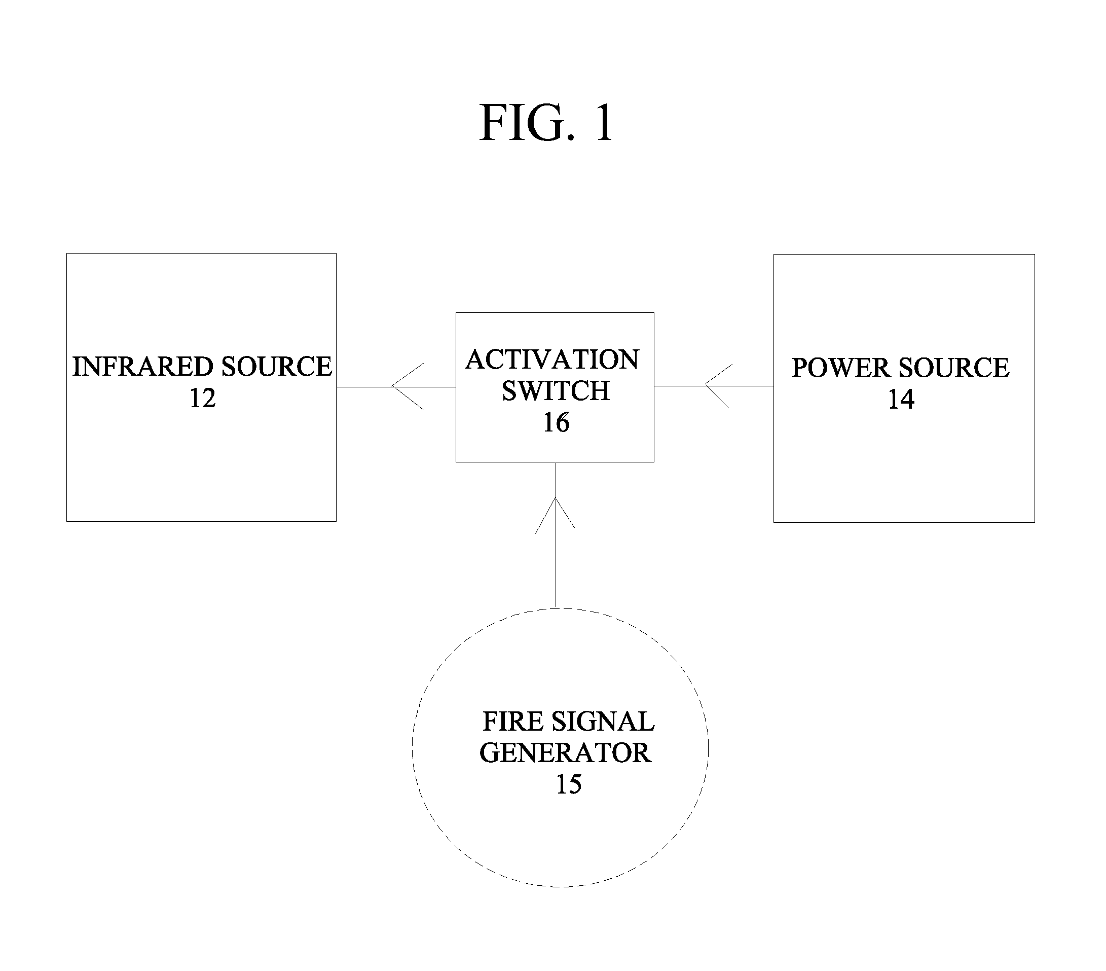
[0043]Referring first to FIG. 1, the thermal imaging beacon 10 of the present invention is shown. The thermal imaging beacon 10 includes an infrared source 12, a power source 14 and an activation switch 16 in communication with the heat source 12 and power source 14. The activation switch 16 is adapted to receive a signal from a fire signal generator 15, such as a smoke detector, or smoke detection system, and to change states to allow power to flow from the power source 14 to the infrared source 12 when a fire has been detected. It is noted that the term “smoke detector” is intended to encompass the term “smoke alarm”, which is also commonly used in the fire protection industry.

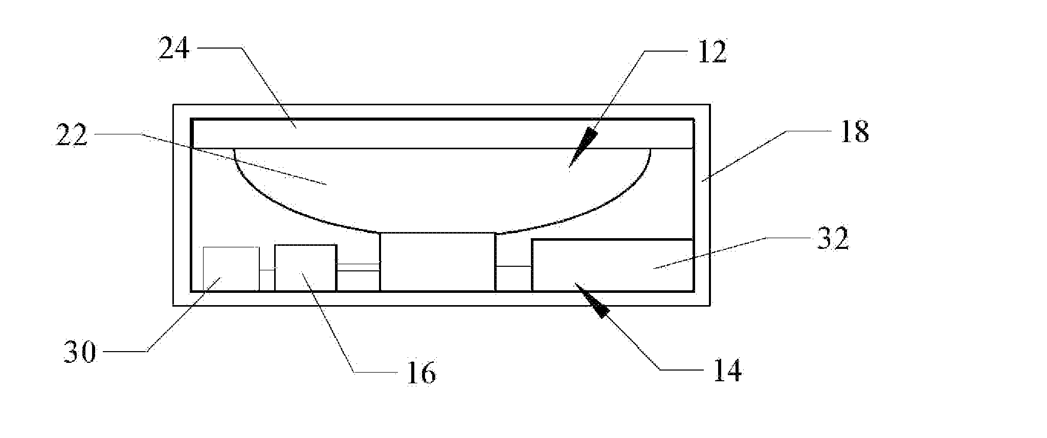
[0044]As shown in FIGS. 2A-2D, the thermal imaging beacon 10 preferably includes a housing 18 within which the in which the infrared source 12, power source 14 and activation switch 16 are disposed. This housing 18 is depicted as being similar to those commonly used in conventional smoke detectors, but it ma...


PUM


Abstract

A thermal imaging beacon, a smoke detector having an integrated thermal imaging beacon, and a thermal imaging beacon system including a thermal imaging beacon and a smoke detector. The thermal imaging beacon includes a heat source, a power source, and an activation switch in communication with the heat source and power source and adapted to allow power to flow to the heat source when the switch is triggered by a fire event signal.

Description

CLAIM OF PRIORITY[0001]This application claims the benefit of priority of U.S. Provisional Patent Application Ser. No. 61 / 767,193, filed on Feb. 20, 2013.FIELD OF THE INVENTION[0002]The present invention relates to fire safety systems and, in particular, to an improved smoke detector that includes a thermal imaging beacon and to stand alone thermal imaging beacons.BACKGROUND OF THE INVENTION[0003]Hundreds of children die each year as a result of residential fires and the majority of these children are those under the age of five. Such children do not have the awareness to leave a burning home and often will attempt to hide in their rooms rather than flee. Thus, firefighters are often forced to search through many rooms of a home to locate and attempt to save young children.[0004]For many years, the “Tot Finder” fire safety program was utilized as an aid to firefighter's location of children in a burning structure. This program advocated the use of window stickers on the outside wind...

Claims


Application Information

Patent Timeline
IPC IPC(8): G08B17/12H04N5/33
CPCH04N5/33G08B17/125G08B1/08G08B7/062G08B17/00A62B5/00H04N23/23
Inventor DOUGHERTY, THOMAS P.
Owner DOUGHERTY THOMAS P
Learn More