
Common mode choke coil and high-frequency electronic device

a choke coil and high-frequency electronic technology, applied in the direction of transformer/inductance details, fixed inductances, inductances, etc., can solve the problems of loss of symmetry property, noise current of a common mode based on asymmetry property, insusceptible to differential transmission methods, etc., to achieve high impedance, large inductance value, and coupling degree between primary coils

Active Publication Date: 2014-08-21
MURATA MFG CO LTD
View PDF3 Cites 15 Cited by
  • Summary
  • Abstract
  • Description
  • Claims
  • Application Information

AI Technical Summary

Benefits of technology

This patent is about a common mode choke coil that reduces loss of normal mode signals and improves removal of common mode noise in a high-frequency band. The coil has two sets of parallel lines wound on one surface, which prevents a displacement in the coil pattern and ensures high coupling between the primary and secondary coils. This results in a high inductance value in the common mode and low impedance in the normal mode, reducing loss of normal mode signals and improving removal of common mode noise. The overall effect is a highly efficient and effective common mode choke coil.

Problems solved by technology

Therefore, the differential transmission method is insusceptible to these noises.
However, in a signal line for a high-speed interface, from a practical perspective, a noise current of a common mode based on the asymmetry property of the signal lines occurs.
Therefore, owing to a problem in a manufacturing process (a position displacement, a stacking displacement, or the like of a coil) or a structural problem (when being mounted in a printed wiring board, a coupling amount between each coil and the ground of the printed wiring board is different), a symmetry property is lost.
However, since the magnetic substance has a relatively large frequency characteristic, in particular a loss of a normal mode signal in a high-frequency band is likely to become large.
In addition, in a case where a sufficient coupling value is not obtained between the primary coil and the secondary coil, the loss of the normal mode signal is likely to become large.

Method used


Image

  • Common mode choke coil and high-frequency electronic device
  • Common mode choke coil and high-frequency electronic device
  • Common mode choke coil and high-frequency electronic device

Examples


Embodiment Construction

[0023]Hereinafter, examples of a common mode choke coil and a high-frequency electronic device according to preferred embodiments of the present invention will be described with reference to accompanying drawings. In addition, in each diagram, a same symbol will be assigned to a component or portion in common, and redundant description will be omitted.

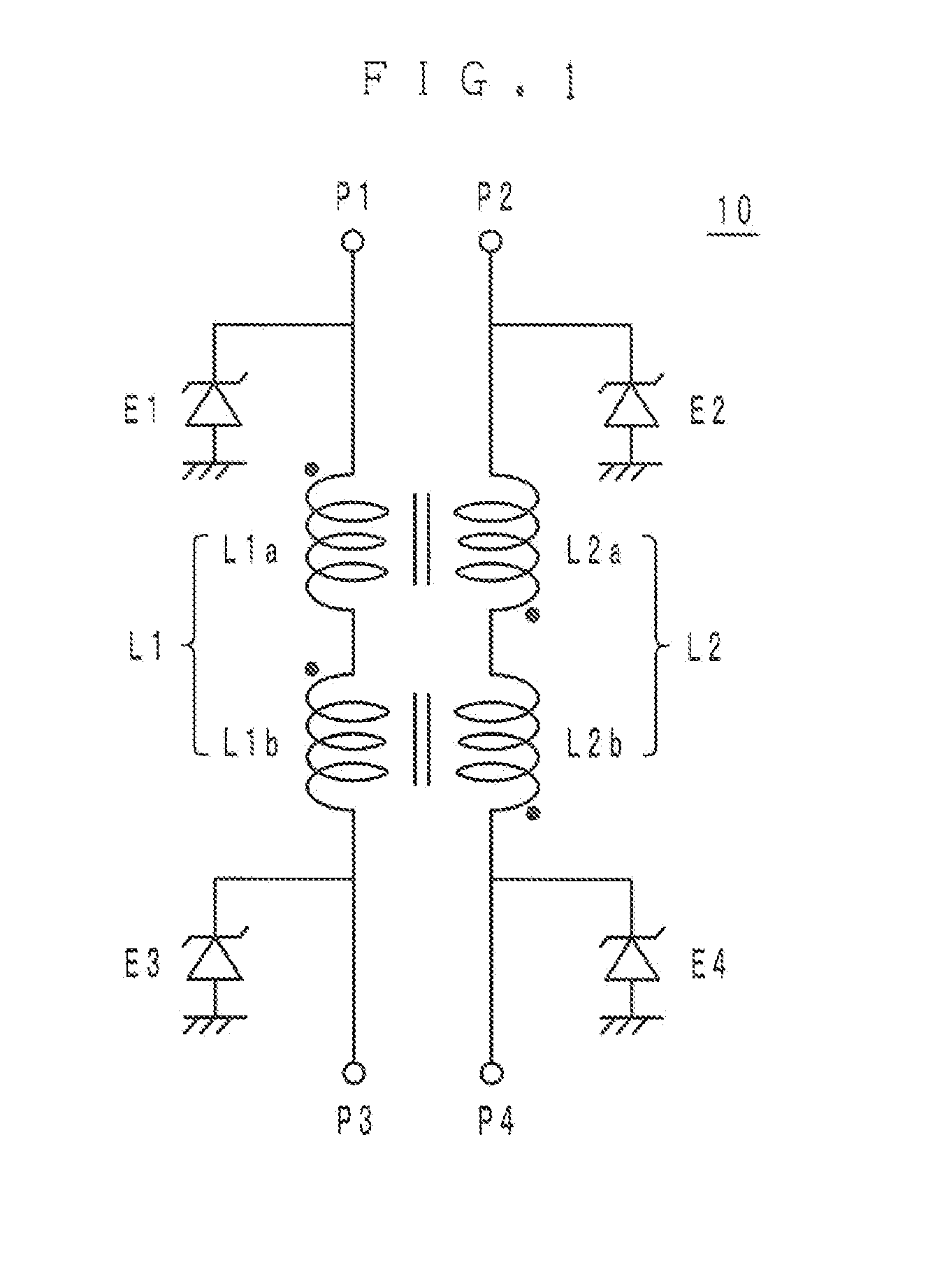
[0024]As illustrated in FIG. 1, a common mode choke coil 10 serving as one example of a preferred embodiment of the present invention includes, as equivalent circuits, a primary coil L1 and a secondary coil L2 coupled to each other through an electromagnetic field. The primary coil L1 includes a coil pattern L1a and a coil pattern L1b connected in series to the coil pattern L1a, and the secondary coil L2 includes a coil pattern L2a and a coil pattern L2b connected in series to the coil pattern L2a.

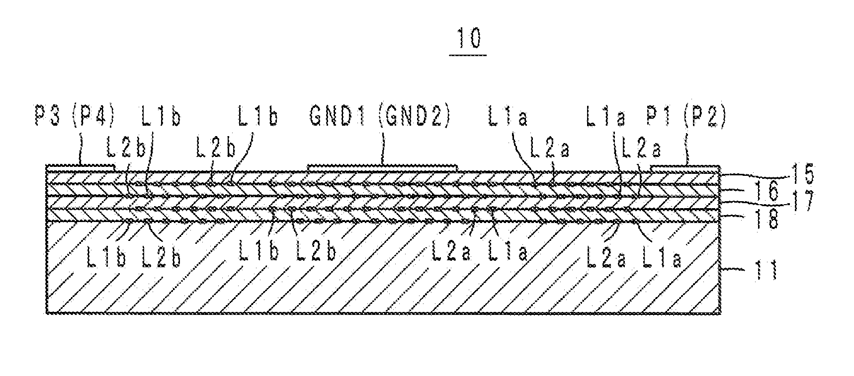
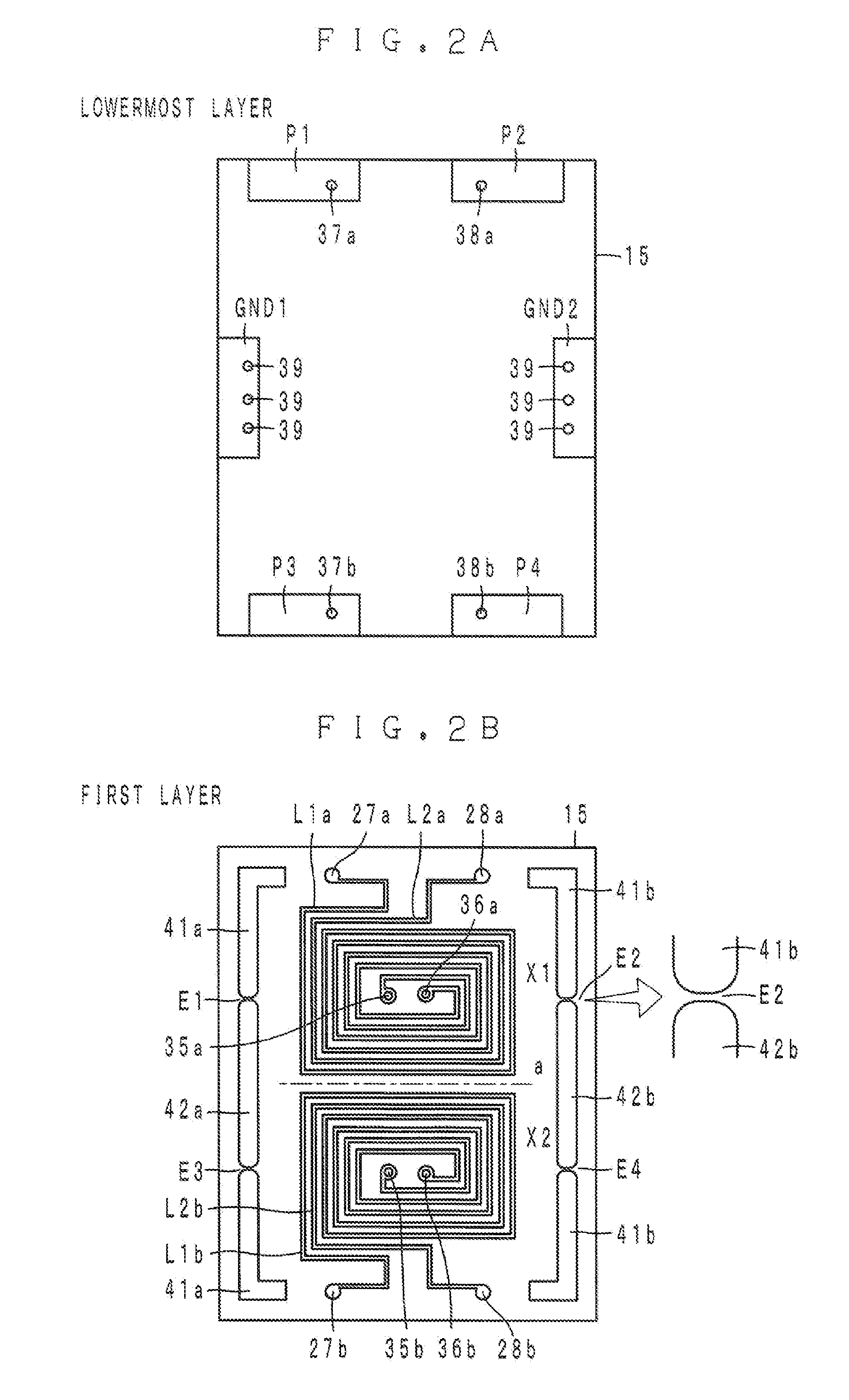
[0025]As illustrated in FIG. 2B, FIGS. 3A and 3B, and FIG. 4, each of the coil patterns L1a, L2a, L1b, and L2b is provided over four layers...


PUM


Abstract

A common mode choke coil includes a primary coil and a secondary coil, wherein the primary coil includes a first coil pattern and a second coil pattern connected in series to the first coil pattern, and the secondary coil includes a third coil pattern and a fourth coil pattern connected in series to the third coil pattern. The first and third coil patterns are concentrically wound, as parallel or substantially parallel lines, in loop shapes on one surface, and the second and fourth coil patterns are concentrically wound, as parallel or substantially parallel lines, in loop shapes on the one surface with being adjacent to the first and third coil patterns.

Description

BACKGROUND OF THE INVENTION[0001]1. Field of the Invention[0002]The present invention relates to a common mode choke coil and a high-frequency electronic device including the common mode choke coil.[0003]2. Description of the Related Art[0004]In the past, in a high-speed interface such as a universal serial bus (USB) or a high definition multimedia interface (HDMI), there has been used a differential transmission method where signals whose phases differ by 180 degrees are transmitted using a pair of signal lines. In the differential transmission method, a radiation noise and an exogenous noise are cancelled out by a balanced line. Therefore, the differential transmission method is insusceptible to these noises. However, in a signal line for a high-speed interface, from a practical perspective, a noise current of a common mode based on the asymmetry property of the signal lines occurs. Therefore, a common mode choke coil that suppresses such a common mode noise is used.[0005]Usually,...

Claims


Application Information

Patent Timeline
IPC IPC(8): H01F27/28
CPCH01F2027/2809H01F27/2804H01F17/0013H01F2017/0073H01F2017/0093
Inventor KATO, NOBORU
Owner MURATA MFG CO LTD
Learn More