
Pool cleaning apparatus and related methods

Active Publication Date: 2014-08-21
RESH INC
View PDF13 Cites 7 Cited by
  • Summary
  • Abstract
  • Description
  • Claims
  • Application Information

AI Technical Summary

Benefits of technology

The invention is about a new type of leaf rake for cleaning swimming pools and similar things. It is designed to be more flexible and easier to assemble and disassemble, while still being effective in cleaning various surfaces in swimming pools. The new leaf rake uses a modular approach to replace parts that wear out, with a retaining member made of at least two different materials. The new leaf rake also has a flexible tip to better conform to different pool surfaces, and it does not compromise the smoothness of the surface being cleaned. This helps to prevent debris from escaping cleaning, and it also reduces the risk of damage to the pool liner. Overall, the new leaf rake is designed to be more efficient, flexible, and effective in cleaning swimming pools.

Problems solved by technology

Since securely retaining the net on the frame is more often a greater concern, the resulting rigidity of the elongated clip / retaining means tends to compromise the ease of assembly, disassembly, and / or replacement of parts.
Further compromise associated with rigidity occurs in the performance of the leaf rake as it is used on various surfaces found in swimming pools, spas, fountains, and other water features.
However, in pools that have soft and smooth surfaces such as vinyl, fiberglass, acrylic, and tile, the benefits of having rigid contact portions of the elongated clip are limited.
When cleaning very smooth and slippery surfaces, the rigid contact portions of a conventional elongated retaining clip tend to glide over such surfaces almost too easily and, as a result, some debris may escape cleaning by either sliding between the clip and the smooth surface or sliding around the leaf net itself.
Said another way, such rigid contact edges can prevent those contact edges from conforming very well to the surface being cleaned—the edges may not be sufficiently flexible.
When cleaning surfaces that have slip reducing textures, this problem may be compounded; very small debris such as sand may easily slide between the textured surface and the contact points of a rigid elongated clip because the rigidity does not allow the contact points to conform to the variations of the textured surfaces.
It is not uncommon for tiny objects such as very small rocks, granules of sand, or other debris to be caught between the vinyl liner and the firm surface upon which it lays, resulting in small bumps in the liner.
As a result, the smoothness of motion that contributes to ease of cleaning is reduced or compromised as the rigid contact points of the cleaning tool grind against the liner.
Furthermore, the small rocks and debris beneath the vinyl liner are potential hazards to the integrity of the vinyl liner, especially if the liner above those rocks and debris is subject to repeated abrasion.
In extreme cases, the integrity of the liner of a vinyl pool may ultimately be compromised to the point where a leak forms in the areas where heavy abrasion occurs (such as from repeated cleanings from a leaf rake).
Other profiles (such as that found on the Purity Red Baron device) are limited in their ability to lift targeted debris.
Whatever the configuration, the rigidity of the elongated clip remains a factor that limits effectiveness in cleaning on some surfaces, especially vinyl liners, fiberglass, acrylic, and tile for the reasons mentioned above.
On the other hand, however, these clip elements typically cannot be made from a material that is too flexible or soft, because such material may be too easily damaged and / or it may not provide the degree of stiffness and structural integrity that is sometimes needed and desired during the cleaning process (for example, to scrape accumulated debris from the bottom of a pool, or to effectively clean a large smooth area of the pool surface).
Those compromises result in similar compromises in the pool leaf rake's performance.

Method used


Image

  • Pool cleaning apparatus and related methods
  • Pool cleaning apparatus and related methods
  • Pool cleaning apparatus and related methods

Examples


Embodiment Construction

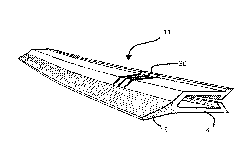
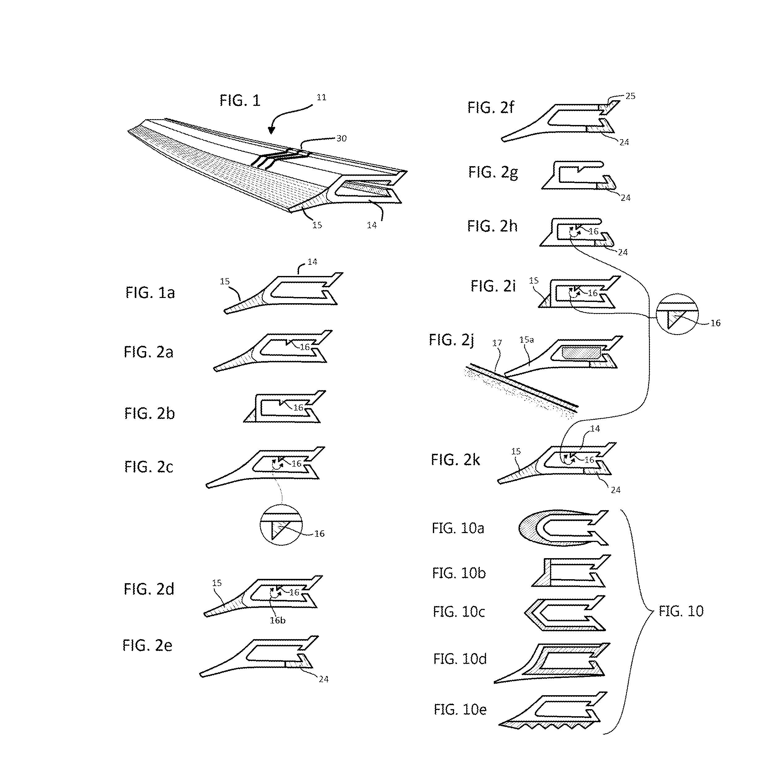
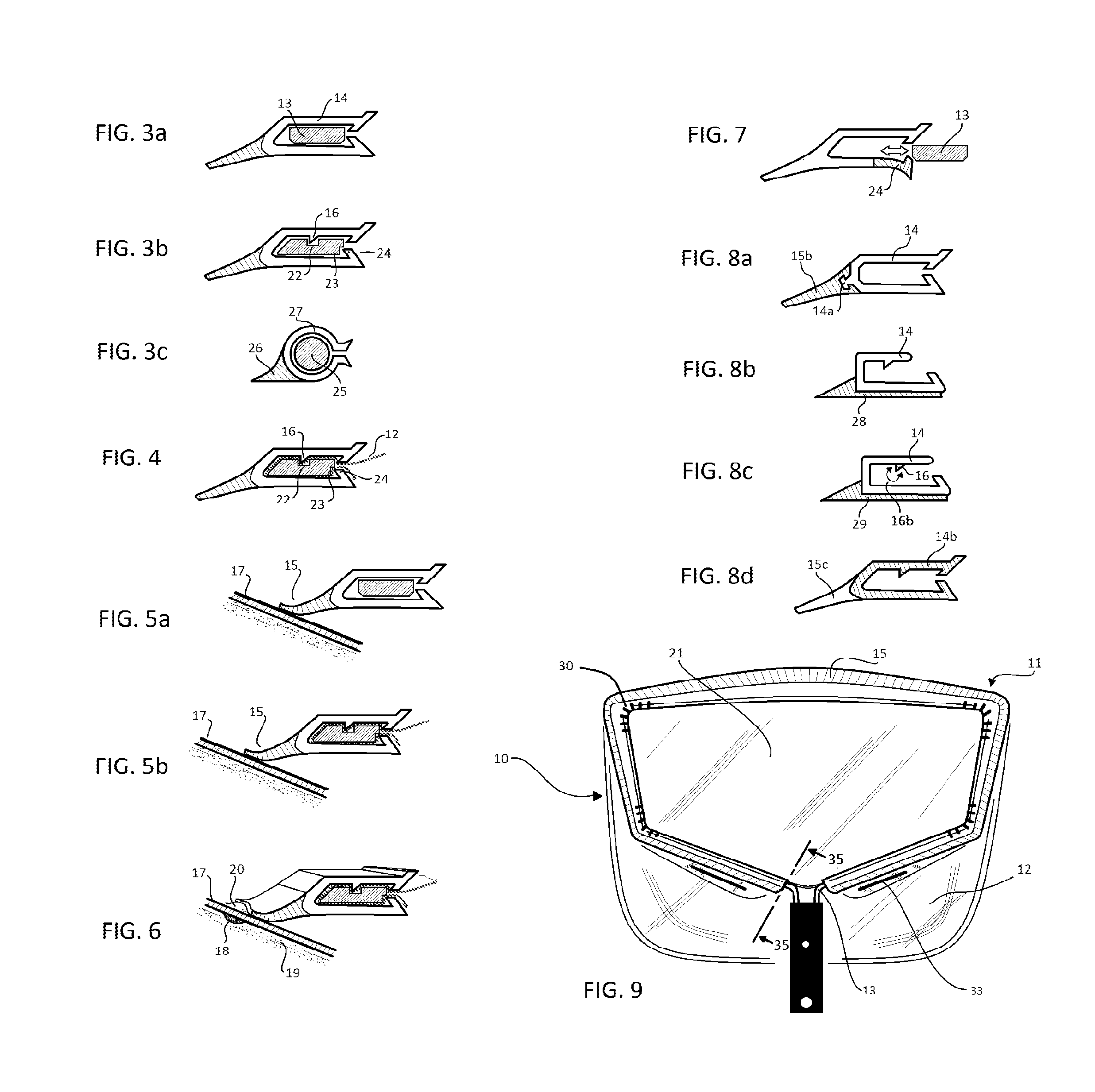
[0058]Referring now to the drawings, and particularly to FIGS. 1, 5a, 5b and 9, a preferred embodiment of a swimming pool cleaning tool 10 is shown including a preferred embodiment of an elongated retaining clip 11 holding a preferred net means 12 on a frame means 13, the net means preferably having anti-slip devices 33 to prevent its edges from slipping between the frame means and the retaining means. Preferably, the retaining means 11 is formed from two different material substances being simultaneously formed into a single piece. In the retaining means, one substance is preferably more rigid than the other. In a preferred embodiment, slots 30 can be cut into designated portions of the retaining means in order to help it conform to the shape of the mouth portion of the frame means. In a preferred embodiment, the two substances are coextruded plastics forming one single elongated retaining means. Preferably, the U-shaped portion 14 of the coextruded retaining means is made of a pla...


PUM


Abstract

A tool for cleaning debris from swimming pools includes a frame, a corresponding net, and retaining means for retaining the net on the frame. The preferred retaining means is an elongated strip of resilient, flexible material, having a generally U-shaped cross-section. The web portion of the cross-section includes an exterior surface smoothly shaped between its two edges to urge debris from the pool into the net. The leg portions of the cross-section include gripping portions to assist in engaging and / or disengaging the retaining means from the frame, to permit the net to be assembled, changed or replaced. Preferably, the retaining means is formed from at least two different materials. The preferred frame of the tool is fabricated from aluminum and includes an elongated, curved frame portion with its ends permanently assembled into the end of a tubular attachment member, to permit attachment of the tool to a handle, pole or similar structure. The preferred net of the tool includes one or more anti-slip devices to prevent the edge of the net or bag from slipping between the frame portion and retaining means. A corresponding preferred method of use is also disclosed.

Description

[0001]This is a continuation-in-part of U.S. Ser. No. 13 / 193,188, filed on Jul. 28, 2011.FIELD OF THE INVENTION[0002]This invention relates to devices for cleaning swimming pools and similar things, and more specifically is directed to apparatus and methods involving a cleaning tool utilizing a frame with a net retained thereon by a retaining member, and the retaining member is formed from at least two different materials.[0003]The disclosures of my previously-issued U.S. Pat. Nos. 5,473,786, 6,302,277, and 6,368,502 are incorporated by reference as if expressly stated herein.BACKGROUND OF THE INVENTION[0004]A wide variety of tools and processes have been developed to clean swimming pools and similar things (fountains, spas—both above and below ground, fish ponds, etc.), including and in addition to those described in my previously-issued U.S. Pat. Nos. 5,473,786 and 6,302,277. Among those devices and methods are devices that are commonly referred to as “leaf rakes”. Commonly, leaf ...

Claims


Application Information

Patent Timeline
IPC IPC(8): E04H4/16
CPCE04H4/1609
Inventor RESH, ERIC
Owner RESH INC
Learn More