Bidirectional mobile cleaning device

Active Publication Date: 2019-08-15
HIZERO APPLIANCES CORP
View PDF5 Cites 1 Cited by
  • Summary
  • Abstract
  • Description
  • Claims
  • Application Information

AI Technical Summary

Benefits of technology

[0004]Based on this, the present disclosure provides a bidirectional mobile cleaning device, which is provided with oppositely-rotating rolling members at ends of a garbage collection box. A speed difference between the rolling members is used to drive the device to move while cleaning, so that the ground can be thoroughly cleaned during both forward and backward motion. Thus, cleaning efficiency is improved.
[0006]In the above-described bidirectional mobile cleaning device, the first rolling member and the second rolling member serve as a cleaning member, and garbage and sewage are fed into the garbage collection box while moving. The first rolling member and the second rolling member nib against the ground. The rotation direction of the first rotting member and the second rolling member are opposite each other. By controlling the difference in rotation speed between the two rolling members, the device can be controlled to move forward or backward. Moreover, since the first rolling member and the second rolling member are respectively disposed at opposite ends of the garbage collection box, whether the device is moving forward or backward, garbage and sewage on the ground can be collected, thereby improving the cleaning efficiency. Through the above design, the oppositely-rotating rolling members are disposed on opposite ends of the garbage collection box, and the device is driven to move based upon the speed difference between the rolling members while cleaning, thereby thoroughly cleaning the ground during forward and backward movement and improving cleaning efficiency.
[0008]In one embodiment, the bidirectional mobile cleaning device further comprises a first brush member and a second brush member located over or in the garbage collection box. The first brush member is configured to remove garbage that adheres to the first rolling member from the first rolling member, and the second brush member is configured to remove garbage that adheres to the second rolling member from the second rolling member. The first brush member rubs against the first rolling member so that the garbage adhering to the first rolling member falls into the garbage collection box, preventing the garbage from being brought back out of the garbage collection box by the first rolling member. The second brush member rubs against the second rolling member so that the garbage adhering to the second rolling member falls into the garbage collection box, preventing the garbage from being brought back out of the garbage collection box by the second rolling member.
[0009]In one embodiment, both the first brush member and the second brush member are rotating brushes. The use of rotating brushes helps to increase the efficiency of the brush members.
[0010]In one embodiment, the bidirectional mobile cleaning device further comprises a first sewage recovery member adjacent to the first rolling member and a second sewage recovery member adjacent to the second rolling member. The first sewage recovery member is used to recover sewage that is absorbed on the first rolling member. The second sewage recovery member is used to recover sewage that is adsorbed on the second rolling member. Sewage that is adsorbed on the first rolling member is recovered through the first sewage recovery member to avoid secondary pollution. Sewage that is adsorbed on the second rolling member is recovered through the second sewage recovery member to avoid secondary pollution.
[0014]In one embodiment, a bottom of the garbage collection box is provided with a load-bearing wheel. The load-bearing wheel serves to relieve the load of the first rolling member and the second rolling member.

Problems solved by technology

The problem with this conventional design is that die garbage behind the flexible roller cannot be effectively cleaned up.
Thus, the conventional bionic cleaning robot has the drawback of being unable to clean thoroughly when moving in reverse, resulting in a decrease in cleaning efficiency.

Method used


Image

  • Bidirectional mobile cleaning device
  • Bidirectional mobile cleaning device

Examples


Embodiment Construction

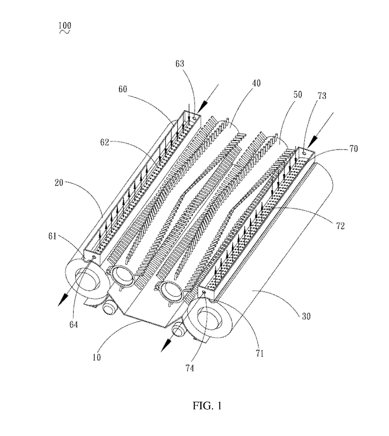
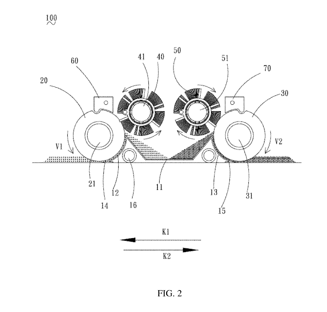
[0030]To facilitate the understanding of the present disclosure, the present disclosure will be described more fully hereinafter with reference to the accompanying drawings. The preferred embodiments of the disclosure are given in the accompanying drawings. However, the present disclosure may he embodied in many different forms and is not limited to the embodiments described herein. Rather, these embodiments are provided so that this disclosure will be thorough and complete. It should be noted that when an element is referred to as being “fixed” to another element, it may be directly on the other element or there may also be an intervening element. When an element is considered to “connect” another element, it can be directly connected to another element or there may be an intervening element. Unless otherwise defined, all technical and scientific terms used herein have the same meaning as commonly understood by one of ordinary skill in the art to which this disclosure belongs. The ...


PUM


Abstract

The disclosure relates to a bidirectional mobile cleaning device comprising a garbage collection box, a first rolling member disposed at one end of the garbage collection box, and a second rolling member disposed at the other end of the garbage collection box. The first rolling member rotates to collect and adsorb garbage and sewage on the ground and feed it into the garbage collection box. The second rolling member rotates in a direction opposite to the direction with which the first rolling member rotates to collect and absorb garbage and sewage on the ground and feed it into the garbage collection box. The bidirectional mobile cleaning device is driven to move based on a speed difference between the first and second rolling members.

Description

RELATED APPLICATIONS[0001]This application is a continuation-in-part of and claims priority to PCT / CN2018 / 076704, filed on Feb. 13, 2018, which is incorporated herein by reference.FIELD OF THE DISCLOSURE[0002]The present disclosure relates to the technical field of bionic cleaning robots, in particular to a bidirectional mobile cleaning device.BACKGROUND OF THE DISCLOSURE[0003]A bionic cleaning robot is an intelligent cleaning device that can automatically clean the ground. Traditional bionic cleaning robots generally use a clean, flexible roller to perform cleaning operations on the ground and have only one, forward cleaning direction. The problem with this conventional design is that die garbage behind the flexible roller cannot be effectively cleaned up. When the bionic cleaning robot reverses direction, the back surface of a garbage scraper lip for scooping the garbage off the ground will scoot the garbage, inhibiting the garbage from being collected and stored in the bionic cle...

Claims


Application Information

Patent Timeline
IPC IPC(8): A47L9/28A47L9/00
CPCA47L9/2847A47L9/2842A47L9/0072A47L9/009A47L2201/04A47L2201/06A47L11/22A47L11/4041A47L11/4013A47L11/4088A47L2201/00A47L11/24
Inventor LI, YANG
Owner HIZERO APPLIANCES CORP
Why Eureka
Try Eureka