
Method for operating a safety control device

a safety control and control device technology, applied in the direction of process and machine control, safety arrangments, instruments, etc., can solve the problems of safety-relevant faults in safety control devices, inability to operate safely, and inability to manually install on the part of a machine operator, etc., to achieve high output signal precision, great precision, and great precision

Active Publication Date: 2014-07-17
PILZ (COMPANY)
View PDF0 Cites 9 Cited by
  • Summary
  • Abstract
  • Description
  • Claims
  • Application Information

AI Technical Summary

Benefits of technology

The new method and device described in this patent use an algorithm called interval arithmetic to increase the precision of calculations and processing of floating point values using a tolerance range. This improves the accuracy of safety control devices and enables the monitoring and control of critical systems with greater precision. The high precision of the output signal can be used to control machines with great precision and safety, such as temperature, pressure, speed of rotation, and position in space.

Problems solved by technology

If these results do not agree, a safety-relevant fault may exist in the safety control device.
As a result, manual intervention in the installation on the part of a machine operative is usually required.
It is disadvantageous that safety control devices are hitherto limited to integer operations.
In this floating point arithmetic, the fundamental rules of algebra are partially inapplicable, since the rules of algebra can be infringed due to the arrangement of the operands around the separator point, and due to a limited length of floating point data types.
It follows from this that when diverse hardware and software components are used for a redundant implementation, comparability of the calculated results cannot be assured.
A safe automation system is not possible in this way.
Neither the precision nor the sequence of operations can, however, be reliably determined, since available compilers and calculation units differ from one another significantly in these aspects.
This would, however, conflict with the basic idea of safe automation, since it is precisely through diverse hardware and software that very high safety is achieved.
However, for the same precision, this leads to a very high memory requirement, which is uneconomical and impractical.
In addition, a precision of the calculation result remains hidden in the approaches described, for which reason again a controller would proceed to operate on the basis of data with potentially any degree of error.
The primary disadvantage in the use of floating point arithmetic in safe automation is therefore not overcome.

Method used


Image

  • Method for operating a safety control device
  • Method for operating a safety control device
  • Method for operating a safety control device

Examples


Embodiment Construction

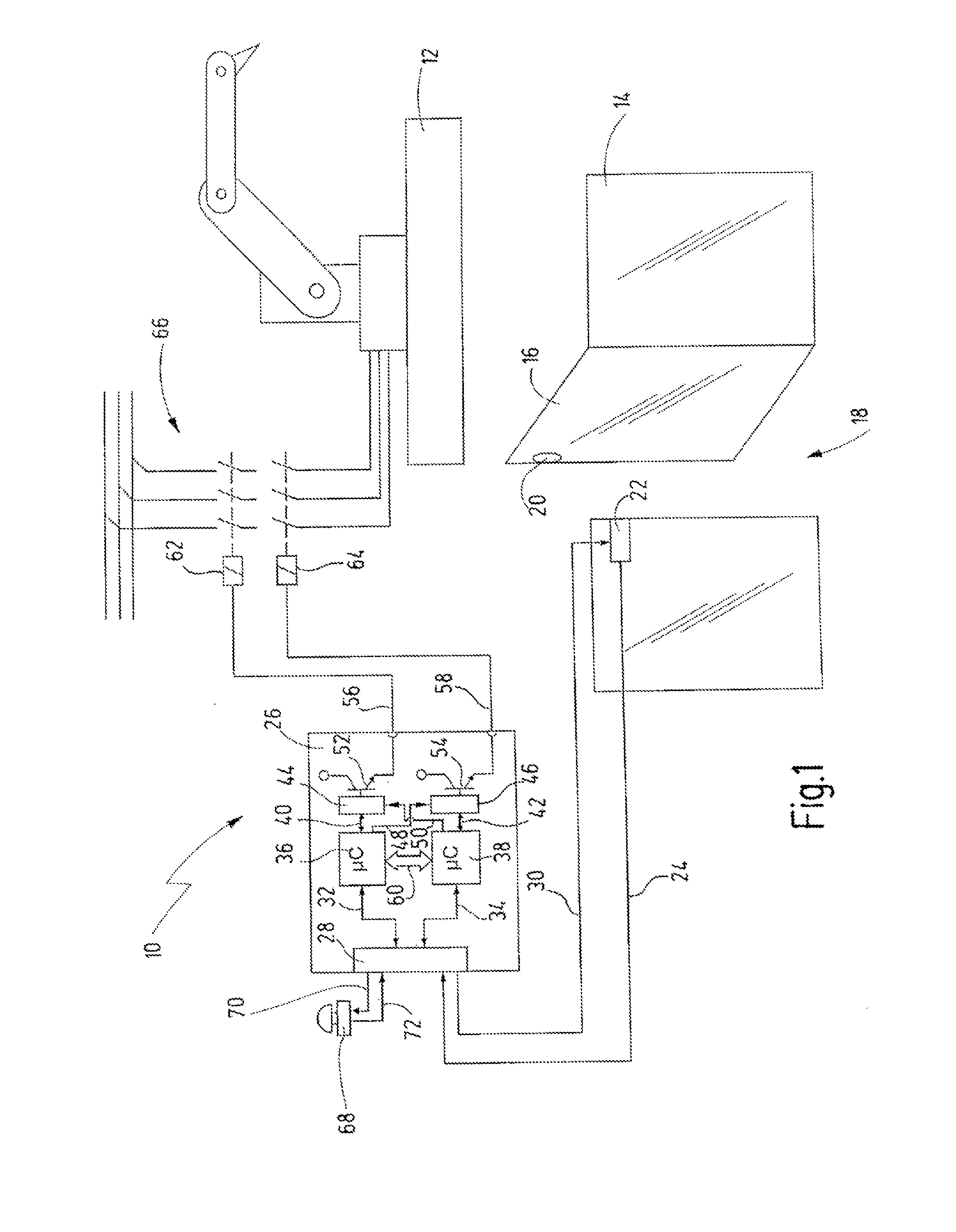
[0096]In FIG. 1 an installation with an exemplary embodiment of the new safety control device is referred to as a whole by reference number 10. The installation 10 contains here for example a robot 12, the movements of which, when in working operation, present a hazard to persons who are in the working area of the robot 12. For this reason, the working area of the robot 12 is secured by a safety fence 14, which comprises a safety door 16. The safety door 16 permits access to the working area, for example for servicing work or for setting-up work. In normal working operation, the robot 12 should only operate when the safety door 16 is closed. As soon as the safety door 16 is opened, the robot 12 must be switched off or brought into a safe state in some other way.

[0097]In order to detect the state of the safety door 16, a safety door switch 18, having a door piece 20 and a frame piece 22, is attached to the safety door 16. The frame piece 22 generates a safety door signal on a cable 2...


PUM


Abstract

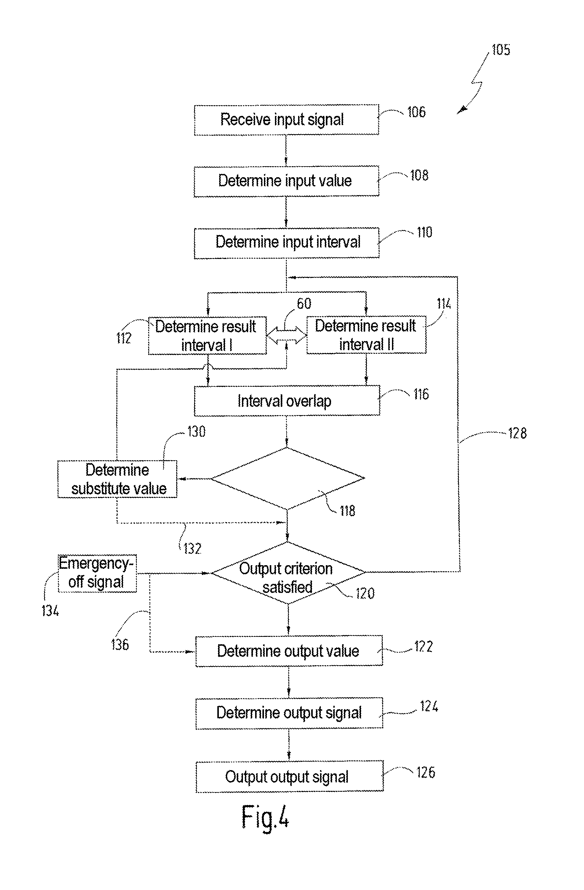
A safety control device for safely controlling a hazardous installation has a first and a second calculation unit and an output unit for driving at least one actuator. The control device acquires an input signal and determines a floating point value depending on the input signal. The first and second calculation units each determine an input interval as a function of the floating point value. The first and second calculation units each further determine a result interval as a function of the input interval by applying a first calculation algorithm to the input interval. The first calculation algorithm is based on interval arithmetic. The result intervals from the first and second calculation units are compared and an output value is determined as a function of the result intervals. An output signal is determined as a function of the output value. The output signal drives the at least one actuator.

Description

CROSS REFERENCES TO RELATED APPLICATIONS[0001]This application is a continuation of international patent application PCT / EP2012 / 057827 filed on Apr. 27, 2012 designating the U.S., which international patent application has been published in German language and claims priority from German patent application DE 10 2011 102 274.4 filed on May 23, 2011. The entire contents of these priority applications are incorporated herein by reference.BACKGROUND OF THE INVENTION[0002]The invention relates to a method for operating a safety control device and a corresponding safety control device.[0003]Safety control devices are usually employed in order to monitor safety-critical areas in industry and to execute a countermeasure in the presence of a safety-critical problem. Safety control devices are typically connected in such a way as to exchange signals on the one hand with indicator devices and on the other hand with actuators. Indicator devices frequently employed for safety control devices in...

Claims


Application Information

Patent Timeline
Patent Type & Authority Applications(United States)
IPC IPC(8): G05B9/03
CPCG05B9/03G05B19/0428G05B2219/14012G05B2219/24003G05B2219/24008G05B2219/24182G05B2219/24188G05B2219/24189G05B2219/24191
Inventor STEGMAIER, SIMONNAWRATIL, TIMOWUELLRICH, JUERGEN
Owner PILZ (COMPANY)
Learn More