
OLED pixel driving circuit

Inactive Publication Date: 2014-07-10
EVERDISPLAY OPTRONICS (SHANGHAI) CO LTD
View PDF2 Cites 14 Cited by
  • Summary
  • Abstract
  • Description
  • Claims
  • Application Information

AI Technical Summary

Benefits of technology

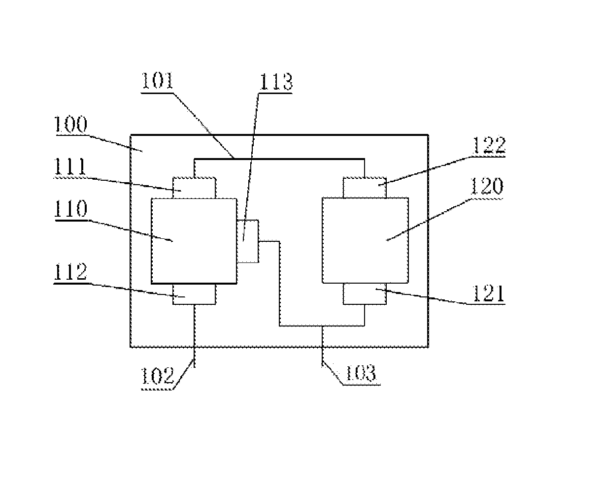
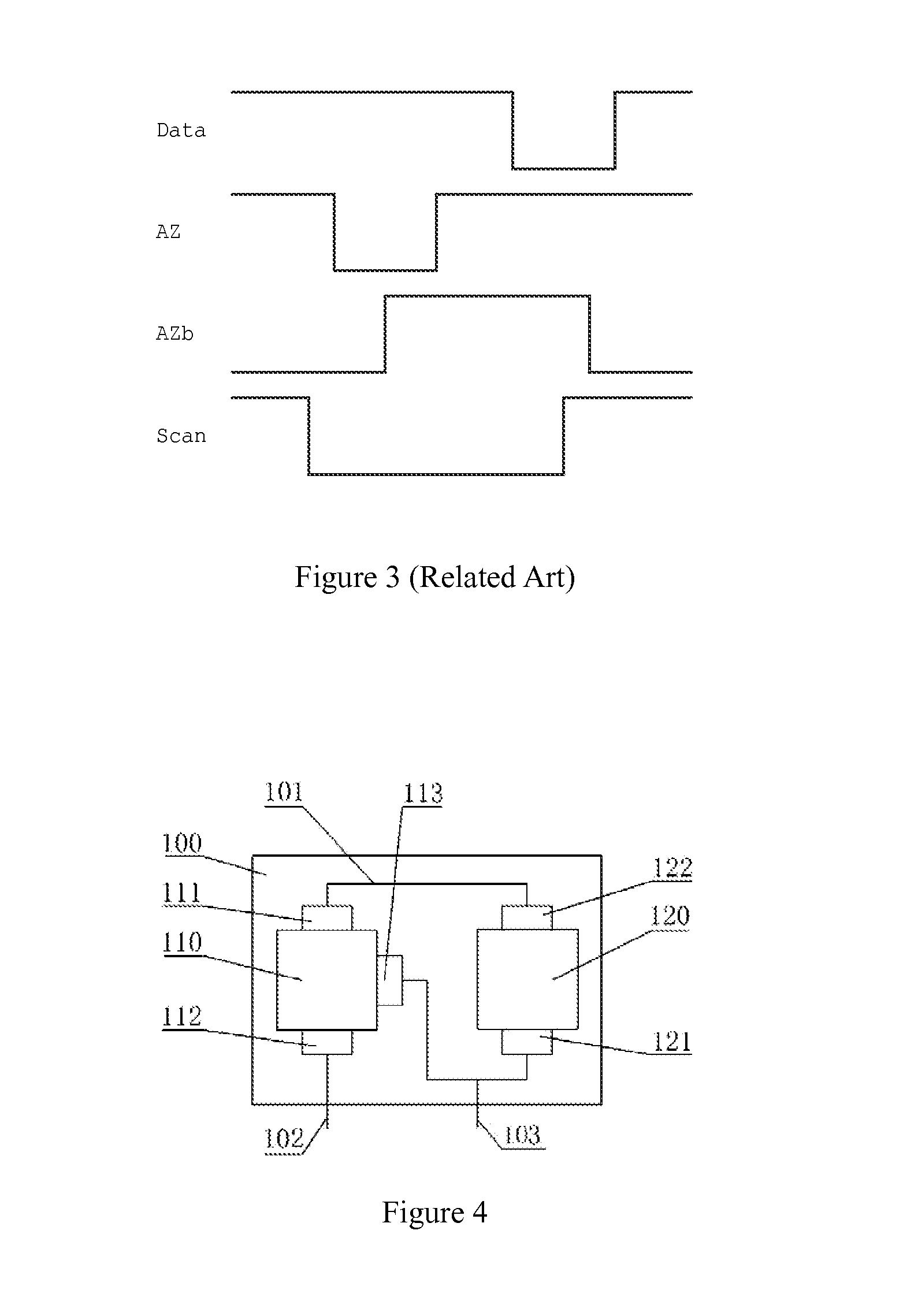
The present invention provides an OLED pixel driving circuit that improves the non-uniformity in the display caused by the threshold voltage drift and power IR drop. This circuit simplifies the driving timing, improves the layout of the flat-screen, and increases the light-emitting time of the OLED in each frame, which enhances the display effect and service life. Additionally, a switch connected to a second power source is used to offset potential loss of the first power source. Overall, the invention improves the performance and brightness of the AM-OLED display.

Problems solved by technology

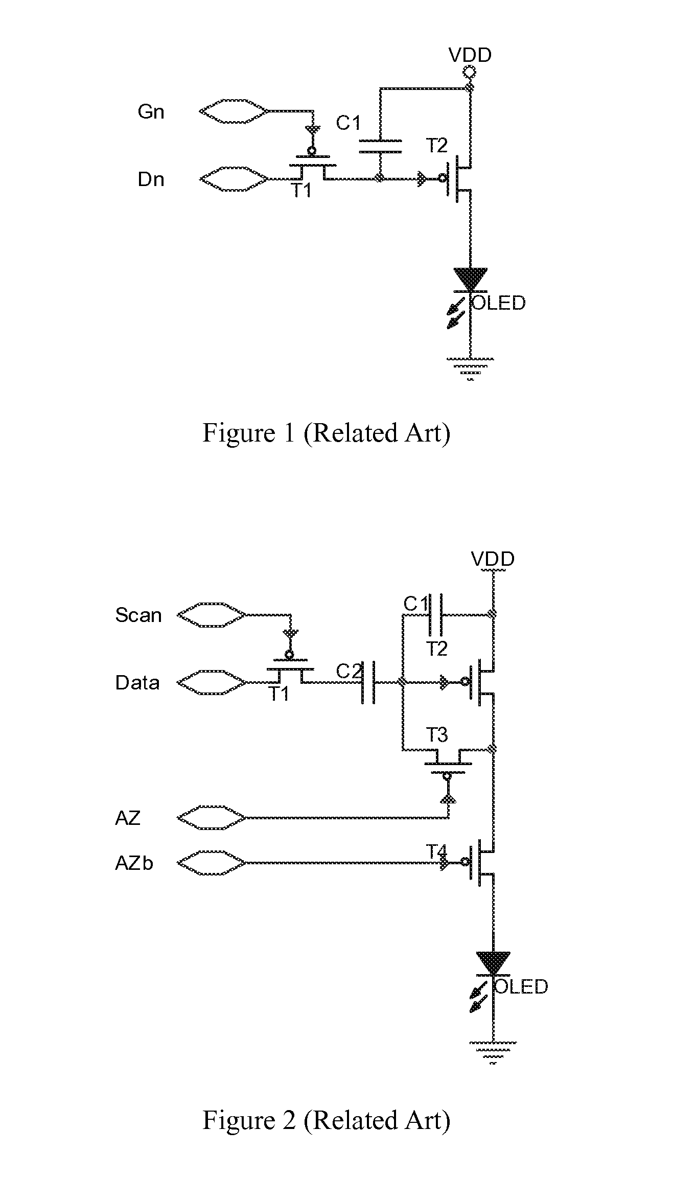
As result of the laser annealing technique applied in the LTPS process, the threshold voltage (Vth) of the transistors has a defect of non-uniformity, whereby there is a large difference between threshold voltages (Vth) among driving transistors.
At the same time, if the pixel power supply line of LTPS transistor is long enough, the pixel circuit power will generate a big IR drop, which may result in a serious non-uniformity in gray-level of the AM-OLED display.
However, such circuit can not compensate the influence of the non-uniformity display of the AM-OLED caused by the non-uniformity of the transistor threshold voltage (Vth) and the IR power drop.
The controlling lines in the adjacent pixel rows cannot be shared and more lines are required in each independent row, which affects the layout inside a panel.
This conventional driving circuit does not meet the requirements to compensate the IR drop and thus a complicated clock structure is used.

Method used


Image

  • OLED pixel driving circuit
  • OLED pixel driving circuit
  • OLED pixel driving circuit

Examples


Embodiment Construction

[0055]The present invention will now be described more fully hereinafter with reference to the accompanying drawings, in which exemplary embodiments of the invention are shown. This invention may, however, be embodied in many different forms and should not be construed as limited to the embodiments set forth herein. Rather, these embodiments are provided so that this disclosure will be thorough and complete, and will fully convey the scope of the invention to those skilled in the art. Like reference numerals refer to like elements throughout.

[0056]The terminology used herein is for the purpose of describing particular embodiments only and is not intended to be limiting of the invention. As used herein, the singular forms “a”, “an” and “the” are intended to include the plural forms as well, unless the context clearly indicates otherwise. It will be further understood that the terms “comprises” and / or “comprising,” or “includes” and / or “including” or “has” and / or “having” when used he...


PUM


Abstract

The present invention relates to an OLED pixel driving circuit which has a data input unit for sending out controlling signals, a voltage storage unit for storing voltages from a first power source, a driving unit for receiving the controlling signals from the data input unit to selectively activate the voltage storage unit, a second power source providing a voltage to be stored in the voltage storage unit; and a switch connected to the second power source to offset potential loss of the first power source from the voltage stored in the voltage storage unit. The compensation circuit can not only compensate the non-uniformity of the threshold voltage but also eliminate the non-uniformity of the OLED display caused by the power IR drop, so that the effect of display of the OLED are maximally improved.

Description

CROSS-REFERENCE TO RELATED APPLICATIONS[0001]The present application claims priority to and the benefit of Chinese Patent Application No. CN201310009175.4, filed on Jan. 10, 2013. The entire content of which is incorporated herein by reference.BACKGROUND[0002]1. Field of the Invention[0003]The present invention generally relates to a circuit, more particularly, to an OLED pixel driving circuit.[0004]2. Description of the Related Art[0005]With Regards to technology of LTPS (Low Temperature Poly-Silicon), it was developed by Japanese and North American technology enterprises in order to reduce the power consumption of notebook-PC display screen and to make the notebook-PC lighter and thinner. The technology of LTPS entered the trial stage in about mid 90's. The new generation OLED (Organic Light Emitting Diode) panel derived from LTPS also formally entered the practical stage in 1998. The advantage of OLED is ultra-thin, lightweight, low power consumption and the characteristics of se...

Claims


Application Information

Patent Timeline
IPC IPC(8): G09G3/32
CPCG09G3/3258G09G2300/043G09G2300/0861G09G2320/045
Inventor QIN, YONGLIANGCHEN, JR HONGHUANG, CHU WAN
Owner EVERDISPLAY OPTRONICS (SHANGHAI) CO LTD
Learn More