
Nozzle capable of deviating a synthetic jet in a dynamic and controllable manner with no moving mechanical parts and a control system thereof

a technology of synthetic jets and nozzles, applied in the direction of spray nozzles, gaseous fuel burners, combustion processes, etc., can solve the problems of poor reliability, poor controllability, and insufficient reliability, and achieve the effect of a particularly simple control of the synthetic j

Inactive Publication Date: 2014-07-10
UNIV DEGLI STUDI DI MODENA E REGGIO EMILIA
View PDF2 Cites 3 Cited by
  • Summary
  • Abstract
  • Description
  • Claims
  • Application Information

AI Technical Summary

Benefits of technology

The present invention provides a nozzle that is easy to use and reliable, and can control the angle of the jet in both static and dynamic modes. This overcomes the limitations of previous designs.

Problems solved by technology

Based on the principles stated, nozzles that can produce a deviation of a fluid jet have been developed in the past, but they offer poor controllability.
To increase the controllability of the jet, particularly complex and not always functional nozzles have been used with movable appendages, or with very high speed pilot jets, resulting in high costs, poor reliability and functional features that are not always adequate.
The device disclosed in US 2009 / 0230209 is rather complicated because, in order to activate or deactivate a control jet, it is necessary to act on a pneumatic valve which controls the single control conduit.
Since a high number of control conduits is provided, the device comprises a number of valves and is therefore relatively expensive and of difficult maintenance.
A drawback of the device disclosed in U.S. Pat. No. 5,894,990 is that the control jet allows the primary jet to be deviated only towards one side, which implies that the primary jet exiting the device can only have a limited number of orientations.

Method used


Image

  • Nozzle capable of deviating a synthetic jet in a dynamic and controllable manner with no moving mechanical parts and a control system thereof
  • Nozzle capable of deviating a synthetic jet in a dynamic and controllable manner with no moving mechanical parts and a control system thereof
  • Nozzle capable of deviating a synthetic jet in a dynamic and controllable manner with no moving mechanical parts and a control system thereof

Examples


Embodiment Construction

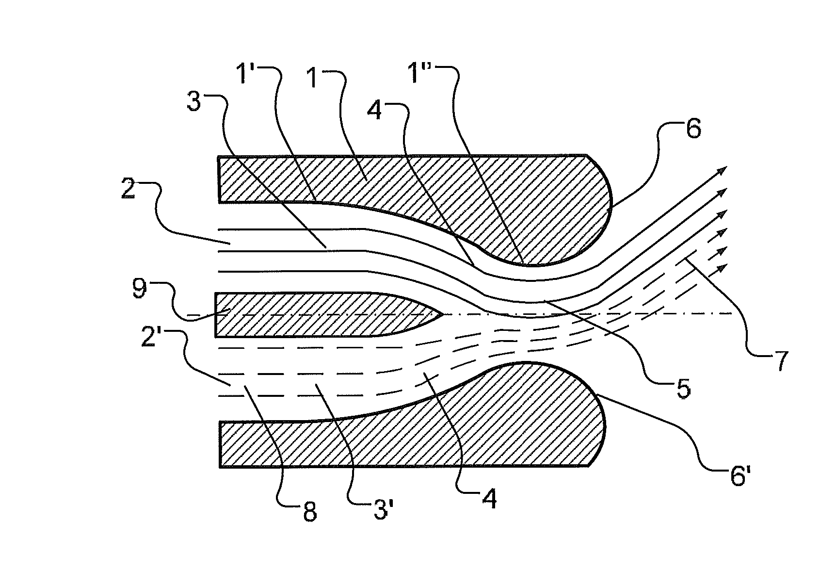
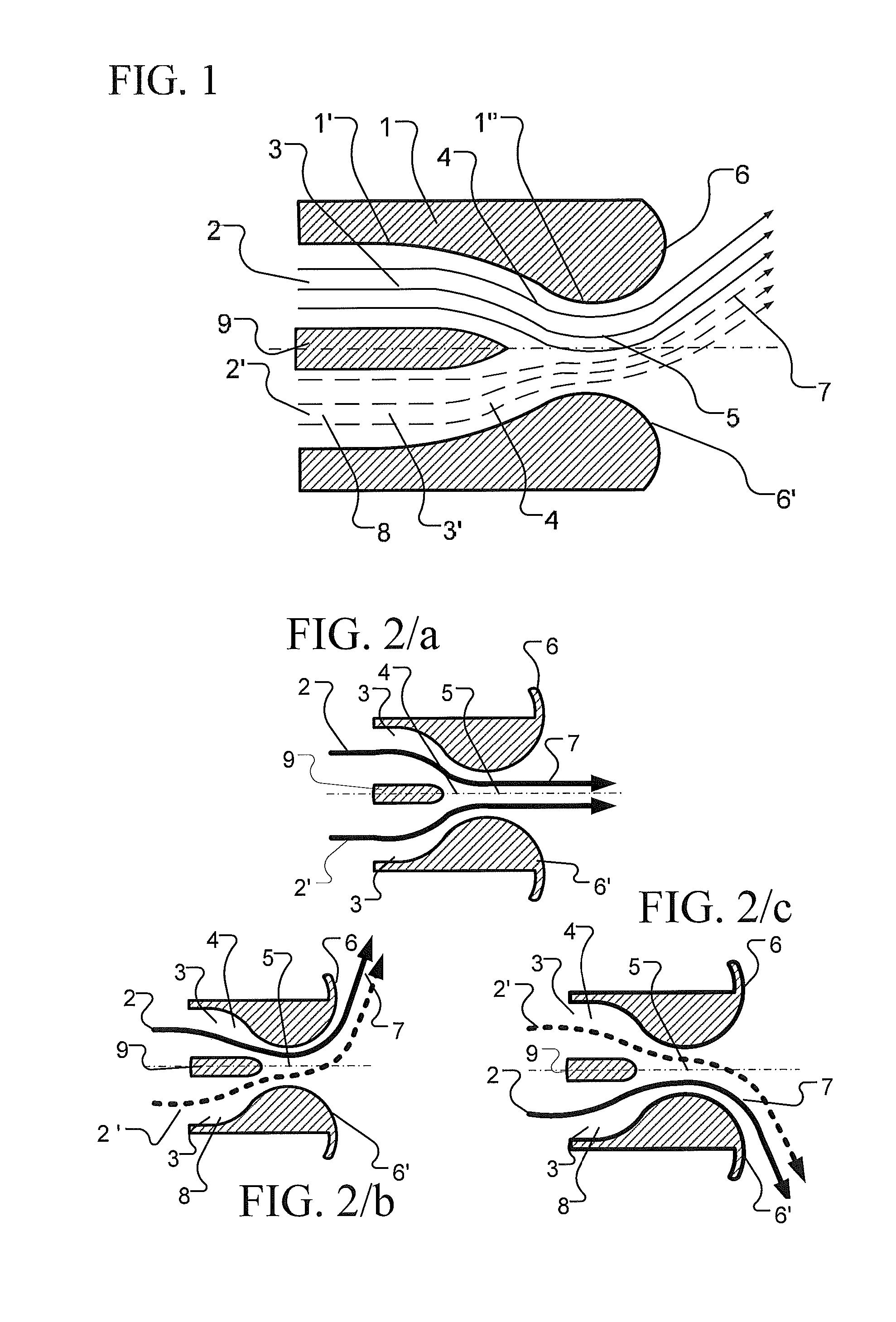
[0027]With particular reference to FIG. 1, (1) indicates a nozzle made according to the present invention and represented in a sectional view.

[0028]This nozzle is constituted by a conduit (8) divided in two half-conduits (3) and (3′) by a separation baffle (9). In other words, the separation baffle (9) divides the conduit (8) in a first channel (3) and in a second channel (3′).

[0029]The length of the separation baffle (9) can be arbitrarily chosen in a design phase.

[0030]A first fluid jet (2) can flow in the first channel (3), whereas a second fluid jet (2′) can flow in the second channel (3′). The fluid jets (2′) and (3′) can be considered as primitive jets intended to be mixed to one another in order to form a resulting jet or synthetic jet.

[0031]Inside the conduit (8) there is defined a zone (1′) designed for the fluid-dynamic stabilization of the primitive jets (2) and (2′), and a zone (1″) constituting a narrowing and leading into the outflow mouth (5), the walls of which are c...


PUM


Abstract

A nozzle is capable of producing a mixing of two primitive fluid jets and a selective and controllable angular deviation of the synthetic jet obtained by mixing the primitive jets without any moving mechanical part. The nozzle is also capable of generating a controllable deviation of the synthetic jet and of changing the direction of this jet in a continuous and dynamic manner so as to allow the jet to sweep a preset and arbitrary angle. The nozzle is constituted, in a first part thereof, by a conduit divided into two channels by a central baffle and, in a second part thereof, by a convergence zone and an outflow mouth whose walls have a curvilinear profile and are connected seamlessly to the walls of the conduit.

Description

FIELD OF THE INVENTION[0001]The object of the present invention is a nozzle capable of producing an angular deviation of a synthetic jet, with no moving mechanical parts, the synthetic jet being formed by mixing more than one primitive jet. The nozzle is also capable of modifying the direction of the synthetic jet in a dynamic manner.[0002]The primitive fluid jets may be homogeneous, that is, equal in nature, physical state and temperature, or non-homogeneous and they can also undergo physical-chemical transformations by virtue of their mixing.[0003]The deviation of the synthetic jet is due to the manner in which the primitive jets mix and to their interaction with the walls.[0004]A suitably shaped nozzle allows such a synthetic jet to adhere to convex walls at the exit from the nozzle itself, in a manner depending on the momentum of the primitive jets (or on the speed, in the case of homogeneous jets) and on the geometry of the walls of the nozzle itself. The adhesion angle can be ...

Claims


Application Information

Patent Timeline
IPC IPC(8): B05B1/00
CPCB05B1/005B05B7/0815F23D14/48F15D1/08F23D14/84F23D2900/14482B05B1/08B05B7/0408
Inventor BAFFIGI, FEDERICADUMAS, ANTONIOGIULIANI, ILARIAMADONIA, MAUROTRANCOSSI, MICHELE
Owner UNIV DEGLI STUDI DI MODENA E REGGIO EMILIA
Learn More