
Positioning Structure for Positioning Optical Film and Frame and Related Backlight Module and Liquid Crystal Display

a technology of positioning structure and optical film, which is applied in the field of liquid crystal display, can solve problems such as unstable z-direction optical film, and achieve the effects of easy assembly, increased assembly speed and capacity, and improved reliability of positioning optical film

Active Publication Date: 2014-07-10
TCL CHINA STAR OPTOELECTRONICS TECH CO LTD
View PDF6 Cites 16 Cited by
  • Summary
  • Abstract
  • Description
  • Claims
  • Application Information

AI Technical Summary

Benefits of technology

The present invention is a positioning structure for optical films that can fix the film in all directions, making it more reliable and easier to assemble. This results in faster assembly times and increased capacity.

Problems solved by technology

This makes the optical film 10 unstable in the Z direction.

Method used


Image

  • Positioning Structure for Positioning Optical Film and Frame and Related Backlight Module and Liquid Crystal Display
  • Positioning Structure for Positioning Optical Film and Frame and Related Backlight Module and Liquid Crystal Display
  • Positioning Structure for Positioning Optical Film and Frame and Related Backlight Module and Liquid Crystal Display

Examples


Embodiment Construction

[0021]In order to illustrate the technique and effects of the present invention, a detailed description will be disclosed by the following disclosure in conjunction with figures. Please note, the same components are labeled by the same number.

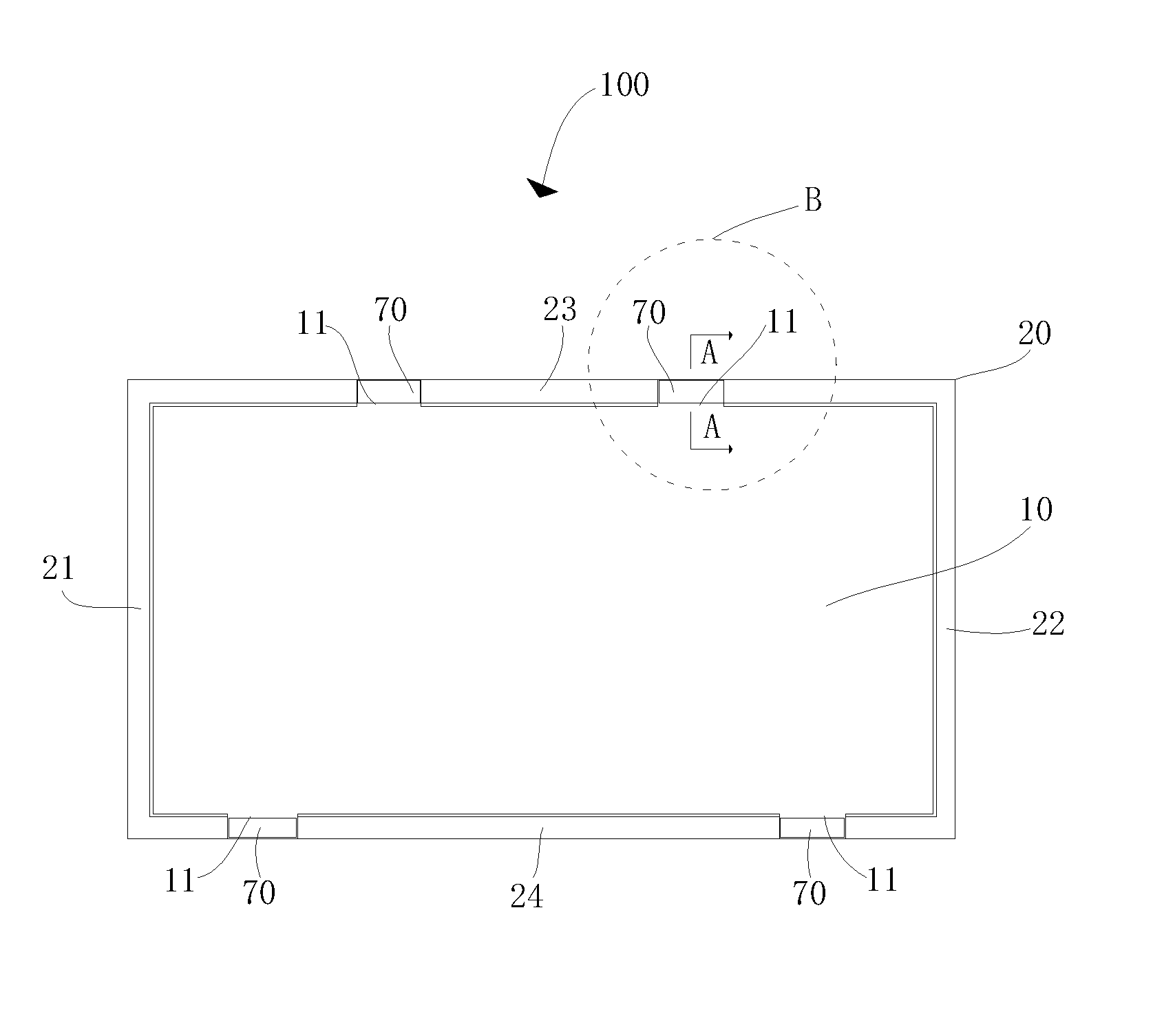
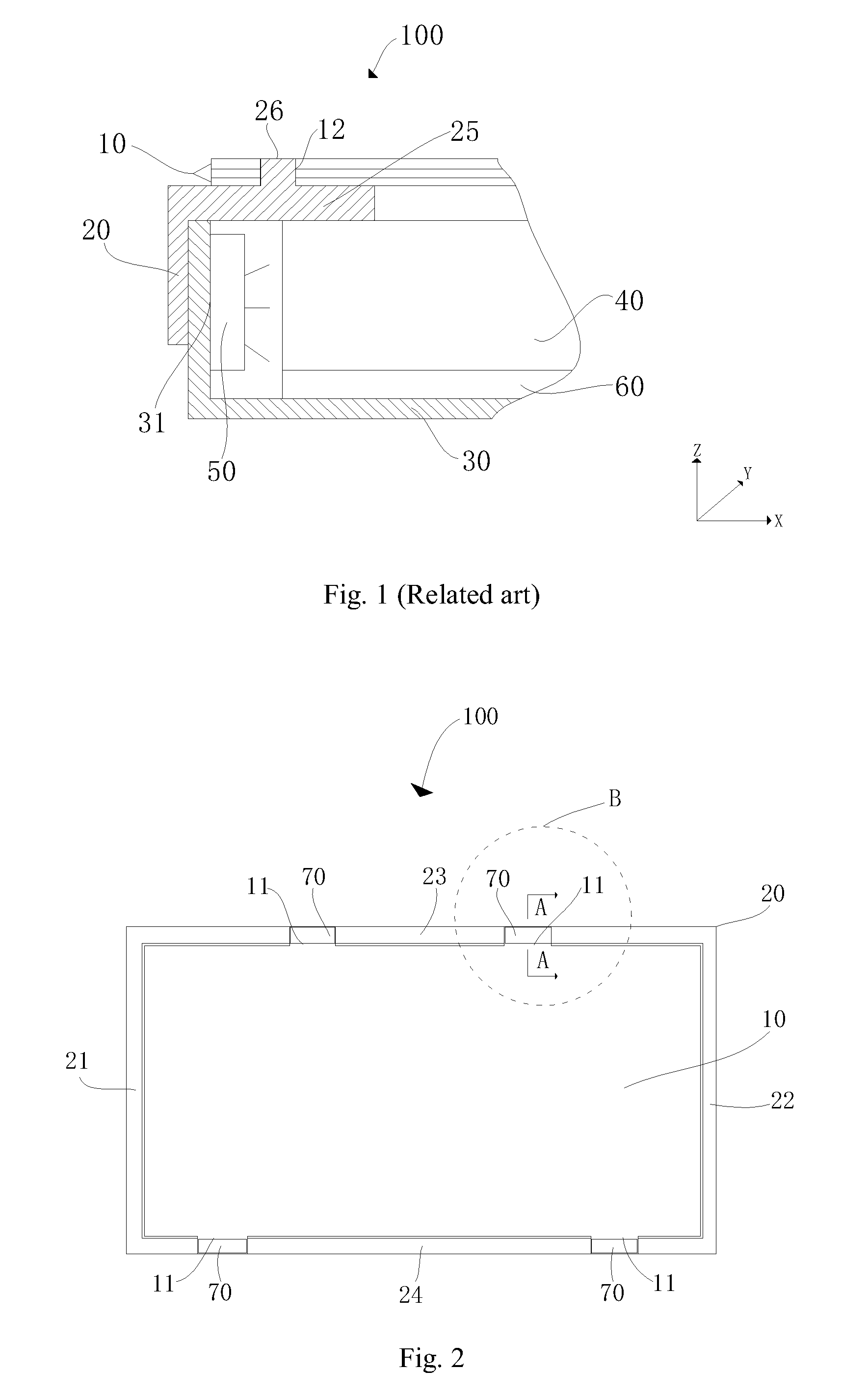
[0022]Please refer to FIG. 2, which is a diagram showing a backlight module according to an embodiment of the present invention. As shown in FIG. 2, the backlight module 100 comprises a plastic frame 20 and at least one optical film 10, where the optical film 10 is installed on the frame.

[0023]Specifically, the plastic frame 20 is a rectangular frame and has four side frames 21, 22, 23, and 24. The first frame 21 and the second frame 22 are installed oppositely, and the third frame 23 and the fourth frame 24 are installed oppositely. Two adjacent frames are vertical to each other. These frames 21, 22, 23, and 24 have the same thickness. In this embodiment, the first frame 21 and the second frame 22 are short side frames of the plastic frame 20,...


PUM

PropertyMeasurementUnit
thicknessaaaaaaaaaa
magneticaaaaaaaaaa
assembling speedaaaaaaaaaa

Abstract

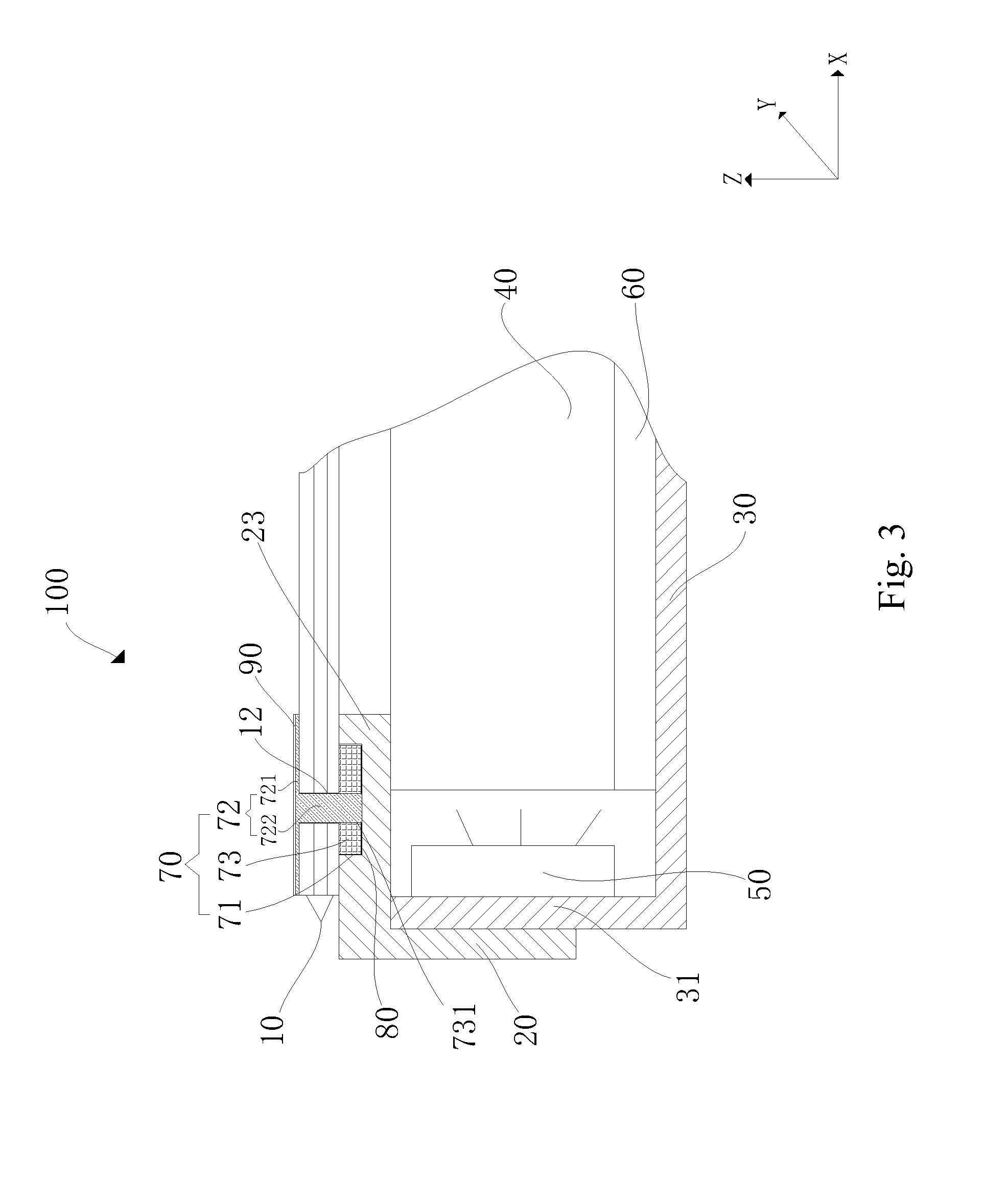
The present invention discloses a backlight module and an LCD having a positioning structure for fixing an optical film and a frame. The frame includes a side frame having an assembling hole. The optical film is placed on the side frame and includes a protruded ear having a positioning hole. The positioning structure includes: a magnetic member installed inside the assembling hole; an attracted member including a compression part and a positioning pillar, wherein the positioning pillar is connected to the compression part and gets inside the assembling hole through the positioning hole such that the positioning pillar is connected to an attraction hole due to a magnetic effect to make the compression part compress and fix the optical film on the side frame. The positioning structure can fix the optical film in X, Y, and Z directions to raise the positioning reliability, assembling speed, and capacity.

Description

BACKGROUND OF THE INVENTION[0001]1. Field of the Invention[0002]The invention relates to a liquid crystal display, and more particularly, to a positioning structure for positioning an optical film and a frame and related backlight module and LCD.[0003]2. Description of the Prior Art[0004]A liquid crystal display (LCD) has many advantages. It has been widely used in all kinds of electronic devices.[0005]In an LCD having a LED backlight module and a narrow side frame, in order to solve a hotspot problem formed on the light guiding plate, the optical film is often placed on the frame. Please refer to FIG. 1, which is a diagram showing a backlight module according to the related art. The backlight module 100 comprises at least one optical film 10, a plastic frame 20, a back frame 30, a light guiding plate 40, and a Led light source 50. The light guiding plate 40 is placed inside the back frame 30. The Led light source 50 is placed on an inner wall 31 of the back frame 30 and near a ligh...

Claims


Application Information

Patent Timeline
Patent Type & Authority Applications(United States)
IPC IPC(8): H01F7/02G02F1/1333A44B99/00F21V8/00
CPCH01F7/02A44B99/00G02B6/0011G02F1/133308G02B6/0085G02B6/0088H01F7/0252G02F1/133608G02F2201/54Y10T24/32
Inventor LI, QUAN
Owner TCL CHINA STAR OPTOELECTRONICS TECH CO LTD
Learn More