
Systems and methods for using a touch-sensitive display unit to analyze a medical image

a touch-sensitive display and image technology, applied in the field of systems and methods that include touch-sensitive display units, can solve problems such as complicating the usability of diagnostic systems

Active Publication Date: 2014-07-03
GENERAL ELECTRIC CO
View PDF13 Cites 19 Cited by
  • Summary
  • Abstract
  • Description
  • Claims
  • Application Information

AI Technical Summary

Benefits of technology

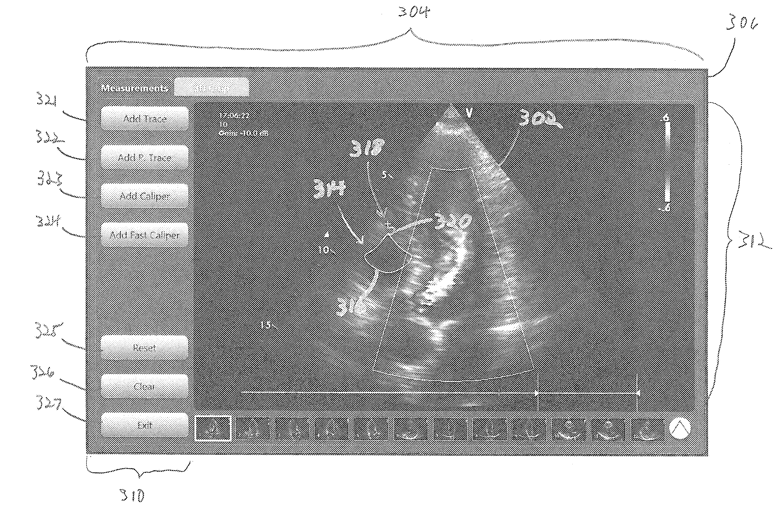
The present patent describes a user interface that includes a touch-sensitive display unit with a user-selectable element that can be moved along a medical image using operator touch. The user-selectable element has an activating portion and a location indicator that move along with the image when activated. The main technical effect is that the interface provides a convenient way for users to modify medical images with a touch of a finger.

Problems solved by technology

Such input devices, however, may require additional space for the diagnostic system and may complicate the usability of the diagnostic system.

Method used


Image

  • Systems and methods for using a touch-sensitive display unit to analyze a medical image
  • Systems and methods for using a touch-sensitive display unit to analyze a medical image
  • Systems and methods for using a touch-sensitive display unit to analyze a medical image

Examples


Embodiment Construction

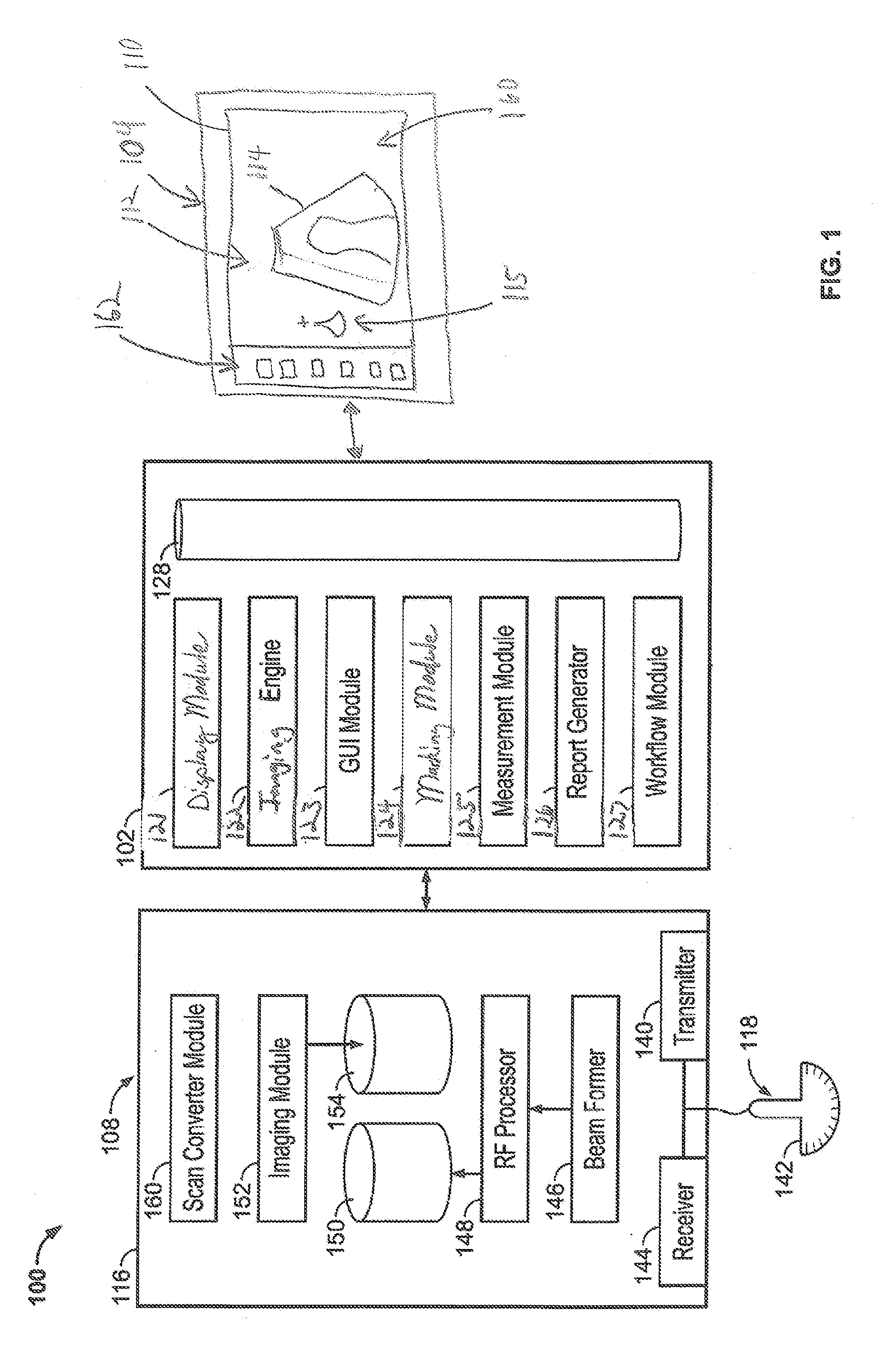
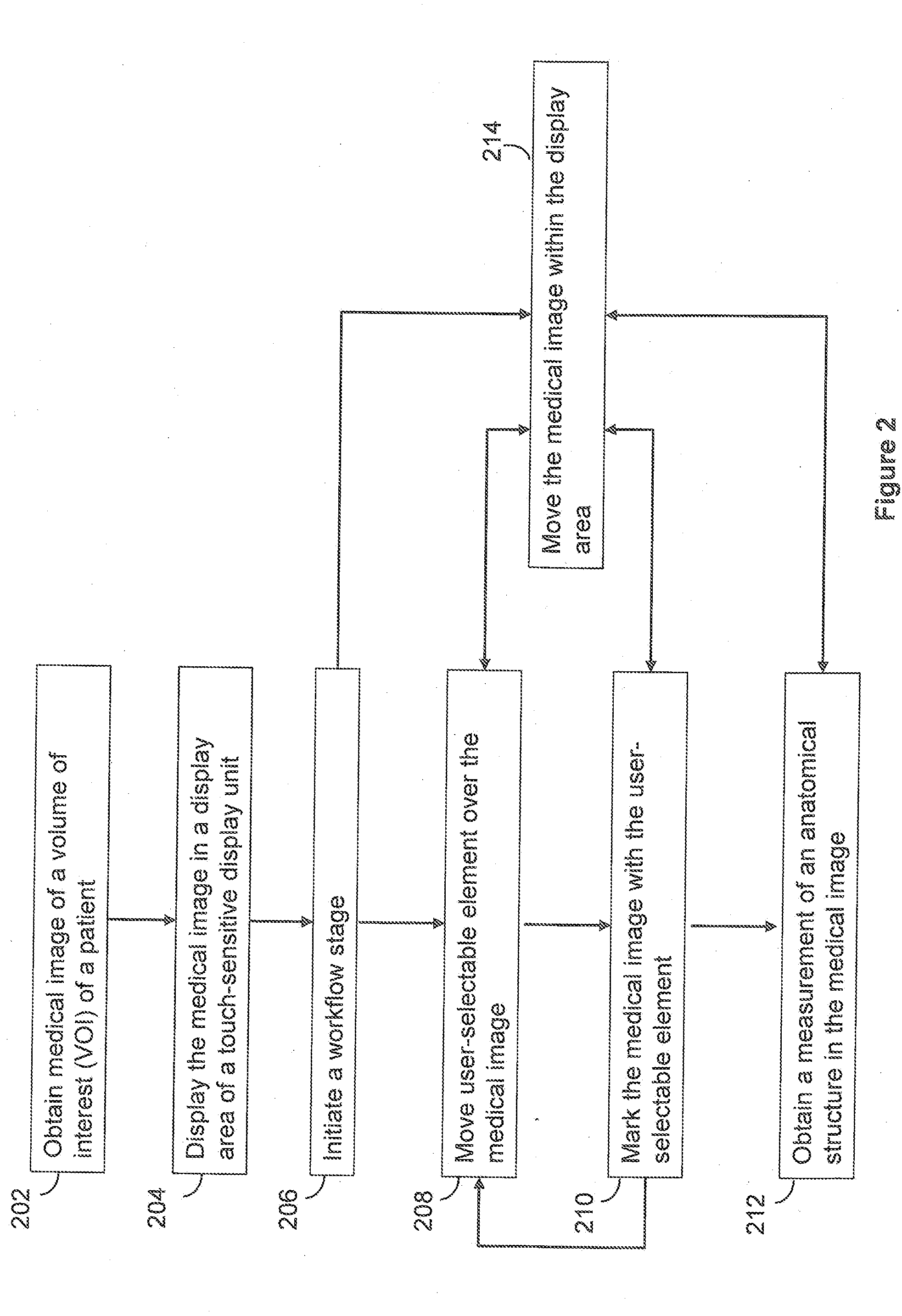
[0016]The following detailed description of certain embodiments will be better understood when read in conjunction with the appended drawings. To the extent that the figures illustrate diagrams of the functional blocks of various embodiments, the functional blocks are not necessarily indicative of the division between hardware circuitry. Thus, for example, one or more of the functional blocks (e.g., processors or memories) may be implemented in a single piece of hardware (e.g., a general purpose signal processor or random access memory, hard disk, or the like). Similarly, the programs may be stand alone programs, may be incorporated as subroutines in an operating system, may be functions in an installed software package, and the like. It should be understood that the various embodiments are not limited to the arrangements and instrumentality shown in the drawings.

[0017]As used herein, an element or step recited in the singular and proceeded with the word “a” or “an” should be unders...


PUM


Abstract

A user interface including a touch-sensitive display unit that has a display area and is configured to show a medical image and a user-selectable element on the display area. The display unit is configured to detect an operator touch and detect a location of the operator touch in the display area. The user-selectable element includes an activating portion and a location indicator. The display unit is configured to move the user-selectable element along the medical image as directed by the operator when the activating portion is touched. The location indicator and the activating portion have fixed positions with respect to each other as the user-selectable element is moved along the display area. The user-selectable element is configured to operate in an activated state and in an inactivated state. The user-selectable element configured to modify the medical image when in the activated state.

Description

BACKGROUND[0001]The subject matter disclosed herein relates generally to systems and methods that enable a user to interact with, analyze, or modify a medical image, and more particularly to systems and methods that include a touch-sensitive display unit.[0002]Patients can be imaged using a wide variety of different imaging technologies. Medical imaging systems may include ultrasound imaging systems, magnetic resonance imaging (MRI) systems, computer tomography (CT) systems, positron emission tomography (PET) systems, single photon emission computed tomography (SPECT) systems, x-ray imaging systems, and others. The medical images include a region-of-interest (ROI) of the patient, e.g., heart, lung, brain, or whole body. The ROI may include anatomical features that are analyzed by healthcare provides or other qualified professionals to diagnose a medical condition.[0003]On some occasions, it may be desirable to analyze the medical images to select certain anatomical features in the m...

Claims


Application Information

Patent Timeline
IPC IPC(8): G06F19/00
CPCG06F19/32G16H40/63G16H30/40
Inventor CASPI, AMIT
Owner GENERAL ELECTRIC CO
Learn More