
Zoom lens system

a zoom lens and lens technology, applied in the field of zoom lens systems, can solve the problems of deteriorating optical quality, difficult to improve optical performance at the design stage, deteriorating optical performance, etc., and achieve the effect of superior optical performance and low error sensitivity

Active Publication Date: 2014-06-26
RICOH IMAGING COMPANY
View PDF3 Cites 4 Cited by
  • Summary
  • Abstract
  • Description
  • Claims
  • Application Information

AI Technical Summary

Benefits of technology

The present invention provides a zoom lens system that includes a negative lens group, a positive lens group, a negative lens group, and a positive lens group, which are arranged in that order from the object side. This system has the advantage of not easily deteriorating during manufacture due to low error sensitivity, and provides a superior optical performance when an image-stabilizing function is provided. Additionally, the third lens group remains stationary in the optical axis direction during zooming from the short focal length to the long focal length. Overall, this invention provides a high-quality zoom lens system that maintains optical performance during image stabilization.

Problems solved by technology

In such a zoom lens system configuration, although there are advantages of being able to miniaturize the image-stabilizing lens group and being able to increase the zoom ratio, there is a disadvantage of deterioration in optical performance occurring during manufacture due to the error sensitivity thereof being high.
Whereas, in the zoom lens system configuration of a negative lens group, a positive lens group, a negative lens group and a positive lens group, in that order from the object side, although there is the advantage of the optical performance, at the design stage, not easily deteriorating during manufacture due to the error sensitivity being low, there is the disadvantage of it being difficult to improve the optical performance at the design stage if the zoom lens system is further miniaturized (and reduced in weight) in order to achieve a high zoom-ratio and / or provide an image-stabilizing function.
However, in the zoom lens system of each of the above-mentioned Japanese Unexamined Patent Publication Nos. 2010-217535 and 2009-14761, since the negative refractive power of the first lens group is too strong compared to the positive refractive power of the second lens group (since the balance of refractive power between the first lens group and the second lens group is inappropriate), resulting in the diameter of the light bundle that is incident on the lens groups that are provided rearwardly from the first lens group (i.e., the second lens group, the third lens group and the fourth lens group) becoming too large, a large amount of coma occurs, thereby deteriorating the optical quality.
Furthermore, since the refractive power of the bonding surface between the positive lens element and the negative lens element of the cemented lens that is provided within the third lens group (the image-stabilizing lens group) is inappropriate, high-order aberrations that occur in the third lens group cannot be sufficiently cancelled out, so that the change in optical performance during an image-stabilizing operation increases, thereby deteriorating the optical performance.
Japanese Unexamined Patent Publication No. 2008-216881 discloses a zoom lens system which is not provided with an image-stabilizing function and is configured of a negative lens group, a positive lens group, a negative lens group and a positive lens group, in that order from the object side; however, even if this zoom lens system were to use the third lens group thereof as an image-stabilizing lens group, and the same problems as those in the zoom lens systems of the above-mentioned Japanese Unexamined Patent Publication Nos. 2010-217535 and 2009-14761 would occur.

Method used


Image

  • Zoom lens system
  • Zoom lens system
  • Zoom lens system

Examples


numerical embodiment 1

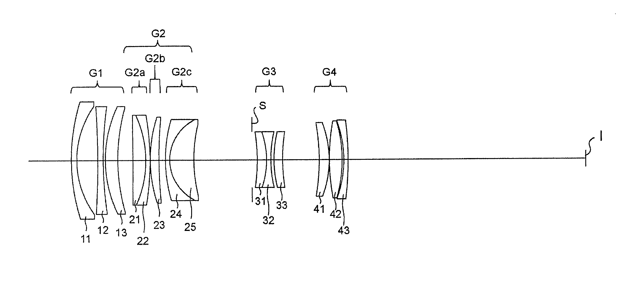
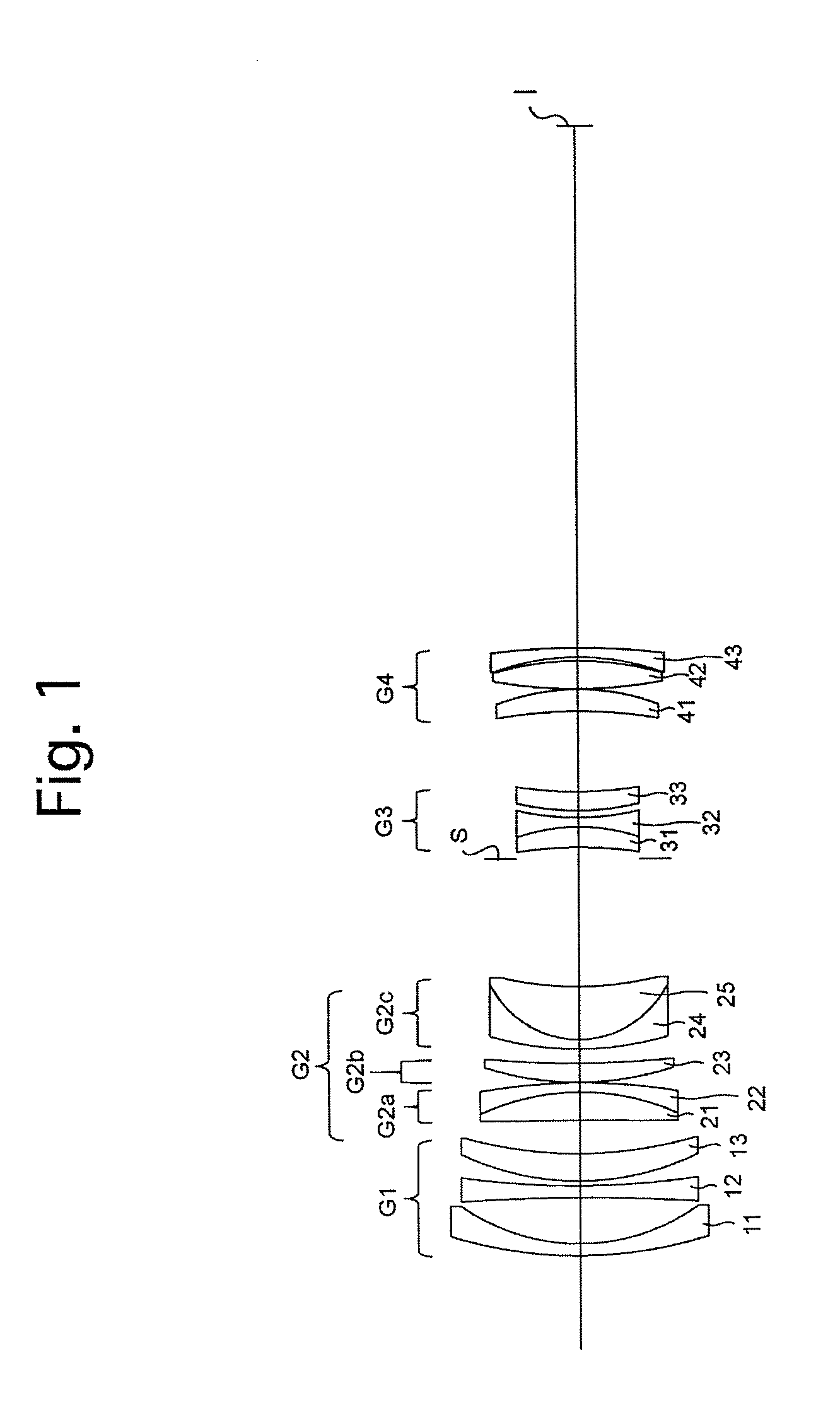
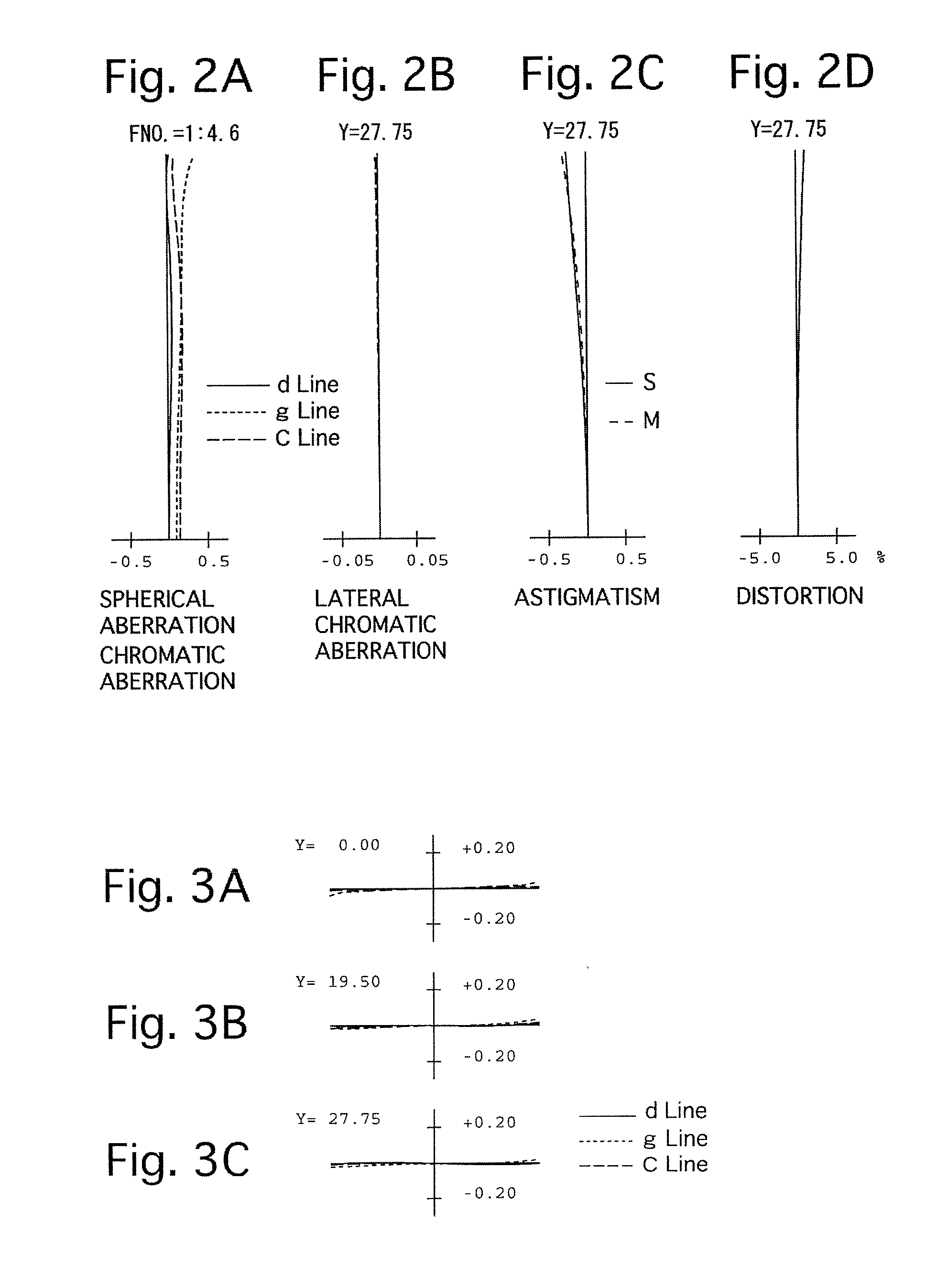
[0103]FIGS. 1 through 6C and Tables 1 through 3 show a first numerical embodiment of a zoom lens system according to the present invention. FIG. 1 shows a lens arrangement of the first numerical embodiment of the zoom lens system at the long focal length extremity when focused on an object at infinity. FIGS. 2A, 2B, 2C and 2D show various aberrations that occurred in the lens arrangement shown in FIG. 1. FIGS. 3A, 3B and 3C show lateral aberrations that occurred in the lens arrangement shown in FIG. 1. FIG. 4 shows a lens arrangement of the first numerical embodiment of the zoom lens system at the short focal length extremity when focused on an object at infinity. FIGS. 5A, 5B, 5C and 5D show various aberrations that occurred in the lens arrangement shown in FIG. 4. FIGS. 6A, 6B and 6C show lateral aberrations that occurred in the lens arrangement shown in FIG. 4. Table 1 shows the lens surface data, Table 2 shows various data of the zoom lens system, and Table 3 shows various data ...

numerical embodiment 2

[0109]FIGS. 7 through 12C and Tables 4 through 6 show a second numerical embodiment of a zoom lens system according to the present invention. FIG. 7 shows a lens arrangement of the second numerical embodiment of the zoom lens system at the long focal length extremity when focused on an object at infinity. FIGS. 8A, 8B, 8C and 8D show various aberrations that occurred in the lens arrangement shown in FIG. 7. FIGS. 9A, 9B and 9C show lateral aberrations that occurred in the lens arrangement shown in FIG. 7. FIG. 10 shows a lens arrangement of the second numerical embodiment of the zoom lens system at the short focal length extremity when focused on an object at infinity. FIGS. 11A, 11B, 11C and 11D show various aberrations that occurred in the lens arrangement shown in FIG. 10. FIGS. 12A, 12B and 12C show lateral aberrations that occurred in the lens arrangement shown in FIG. 10. Table 4 shows the lens surface data, Table 5 shows various data of the zoom lens system, and Table 6 shows...

numerical embodiment 3

[0112]FIGS. 13 through 18C and Tables 7 through 9 show a third numerical embodiment of a zoom lens system according to the present invention. FIG. 13 shows a lens arrangement of the third numerical embodiment of the zoom lens system at the long focal length extremity when focused on an object at infinity. FIGS. 14A, 14B, 14C and 14D show various aberrations that occurred in the lens arrangement shown in FIG. 13. FIGS. 15A, 15B and 15C show lateral aberrations that occurred in the lens arrangement shown in FIG. 13. FIG. 16 shows a lens arrangement of the third numerical embodiment of the zoom lens system at the short focal length extremity when focused on an object at infinity. FIGS. 17A, 17B, 17C and 17D show various aberrations that occurred in the lens arrangement shown in FIG. 16. FIGS. 18A, 18B and 18C show lateral aberrations that occurred in the lens arrangement shown in FIG. 16. Table 7 shows the lens surface data, Table 8 shows various data of the zoom lens system, and Table...


PUM


Abstract

A zoom lens system includes a negative first lens group, a positive second lens group, a negative third lens group, and a positive fourth lens group. Upon zooming from the short to the long focal length extremities, the distance between the first and second lens groups decreases, the distance between the second and third lens groups increases, and the distance between the third and fourth lens groups decreases. The following conditions (1) and (2) are satisfied:−2.50<f1 / f2<−1.57  (1),andf3 / f3B<−0.1  (2),whereinf1, f2 and f3 designate the focal lengths of the first, second and third lens groups, respectively, and f3B designates the focal length of a bonding surface in the cemented lens of the third lens group.

Description

BACKGROUND OF THE INVENTION[0001]1. Field of the Invention[0002]The present invention relates to a zoom lens system which includes a standard focal-length range to a intermediate telephoto range.[0003]2. Description of Related Art[0004]Zoom lens systems which includes a standard focal-length range to a intermediate telephoto range and which is configured of four lens groups, i.e., a configuration of a positive lens group, a negative lens group, a positive lens group and a positive lens group, in that order from the object side, or a configuration of a negative lens group, a positive lens group, a negative lens group and a positive lens group, in that order from the object side, are known in the art.[0005]In the zoom lens system configuration of a positive lens group, a negative lens group, a positive lens group and a positive lens group, in that order from the object side, it is predominant for such a zoom lens system to have a function for correcting hand-shake (image-stabilizing f...

Claims


Application Information

Patent Timeline
Patent Type & Authority Applications(United States)
IPC IPC(8): G02B15/177
CPCG02B15/177G02B27/646G02B15/144511
Inventor SAORI, MASAKAZU
Owner RICOH IMAGING COMPANY
Learn More