Portable Diopter Meter

a diopter meter and portability technology, applied in the field of portable diopter meter, can solve the problems of increasing the optical power of the eye, increasing the convexity of the lens, and severe lack of trained eye care professionals that can perform the rather complicated procedure of phoropter refraction, so as to facilitate the use of the device and screen for refractive error problems. the effect of easy and quick holding

Inactive Publication Date: 2014-06-26
SPIVEY BRETT +1
View PDF5 Cites 16 Cited by
  • Summary
  • Abstract
  • Description
  • Claims
  • Application Information

AI Technical Summary

Benefits of technology

[0015]The present invention, the portable diopter meter, is an inexpensive, easy-to-use self-refracting device which adjusts to continuously variable prescription corrections for a patient. The unit is small enough so that the patient can easily hold the device, and look through the device as if it were a set of glasses. In preferred embodiments specially designed gear arrangements, controlled by control knobs, moves one lens relative to the other or both lenses relative to each other in directions perpendicular to the viewing direction. The patient turns the device's knobs until vision is clearest. Unlike in a phoropter, where discrete correction values are offered by the eye care professional, the portable diopter meter allows for smooth and continuous change of refractive power while the patient is viewing an object. Once the patient adjusted the device for best vision, the patient's prescription can be read off various scales on the device. The diopter meter, therefore, can be used to easily and quickly screen for refractive error problems by allowing patients to self-adjust power and, if refractive error is present, see for themselves how much better they could see with corrective glasses.
[0016]The variable lens technology used in the diopter meter is a variant of the Alvarez variable lens technology discussed in the Background section. This technology has been combined with a simple mechanism Applicants have developed to implement the adjustable prescription correction. The device described here is lightweight, low cost, and simple to use.
[0018]The patient then closes one eye, or an occluder is used to cover one eye, and the patient adjusts the knob for the lens in front of the other, non-occluded eye, until vision is sharpest. Then, the patient is asked to turn the knob towards more positive diopter readings until his / her vision is just starting to become blurry. This step is used to avoid over-correcting a patient's eye due to accommodation.

Problems solved by technology

This results in increased convexity of the lens which in turn increases the optical power of the eye.
In many parts of the world, in particular in developing countries, there is a severe lack of trained eye care professionals that can perform the rather complicated procedure of a phoropter refraction.
Therefore, many people have never been examined for refractive error and do not know if they see as well as they could by simply wearing glasses.
However, these computerized devices are fairly expensive, require electrical power, and need regular maintenance and service by trained personnel, none of which is available in many developing countries.

Method used


Image

  • Portable Diopter Meter
  • Portable Diopter Meter
  • Portable Diopter Meter

Examples


Embodiment Construction

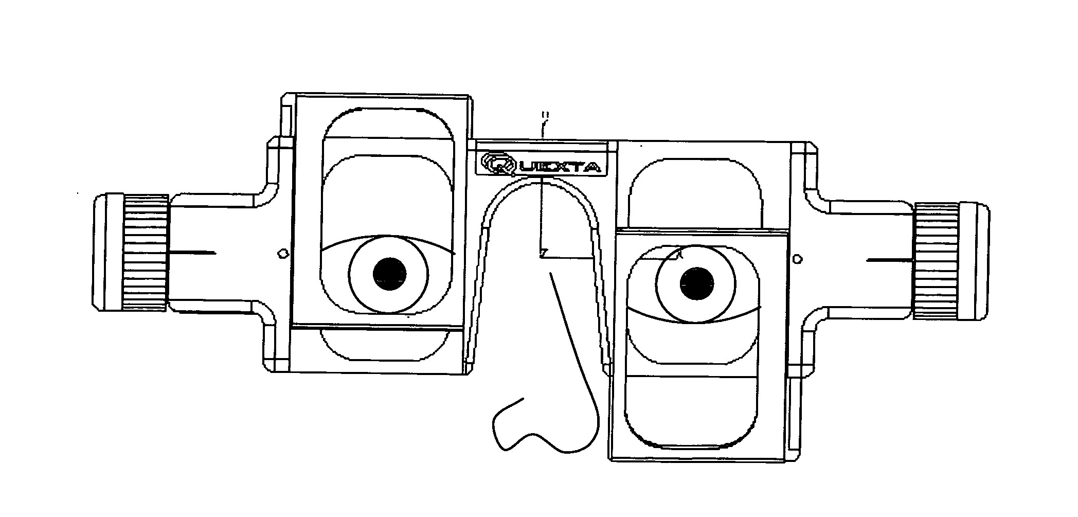
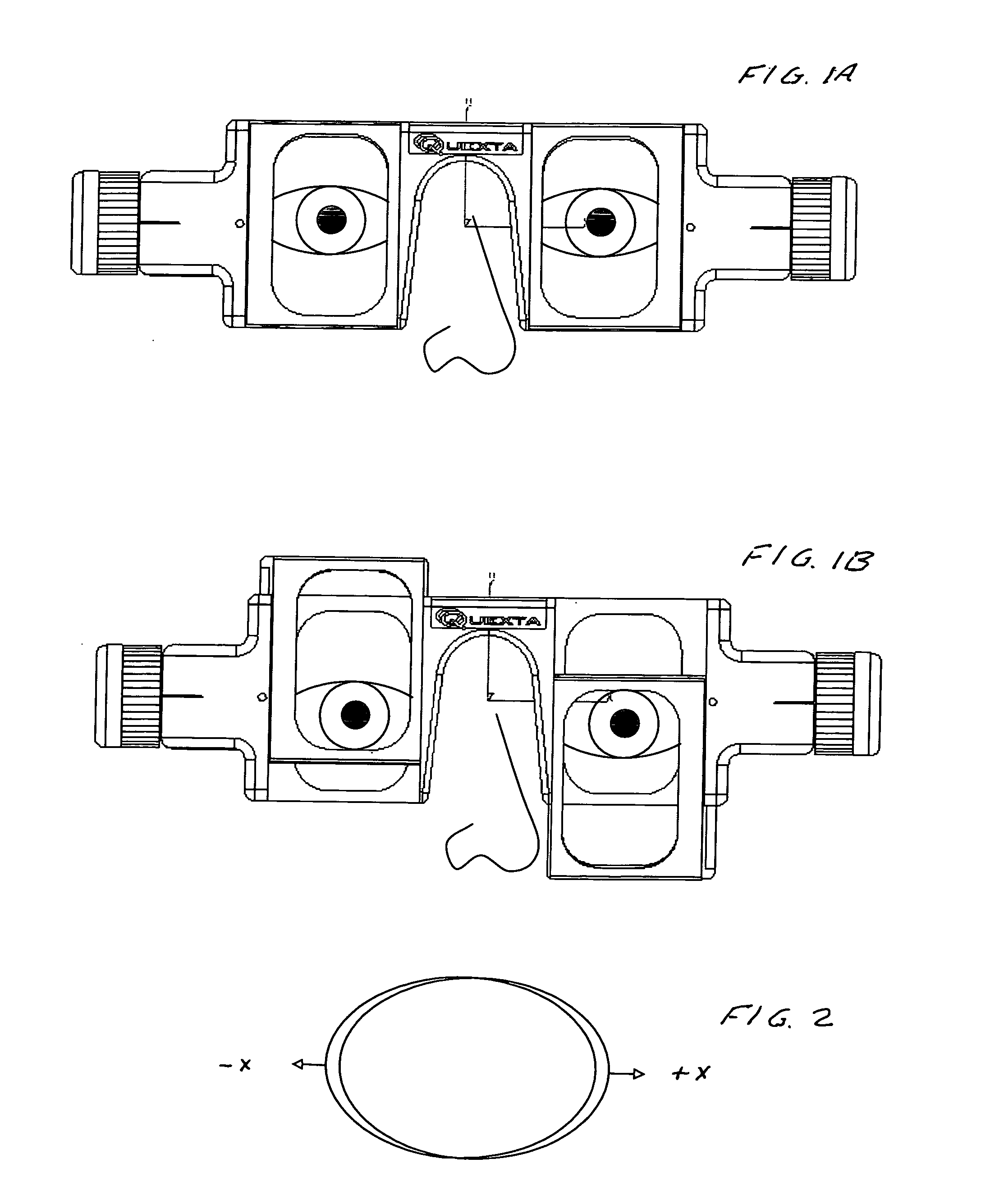
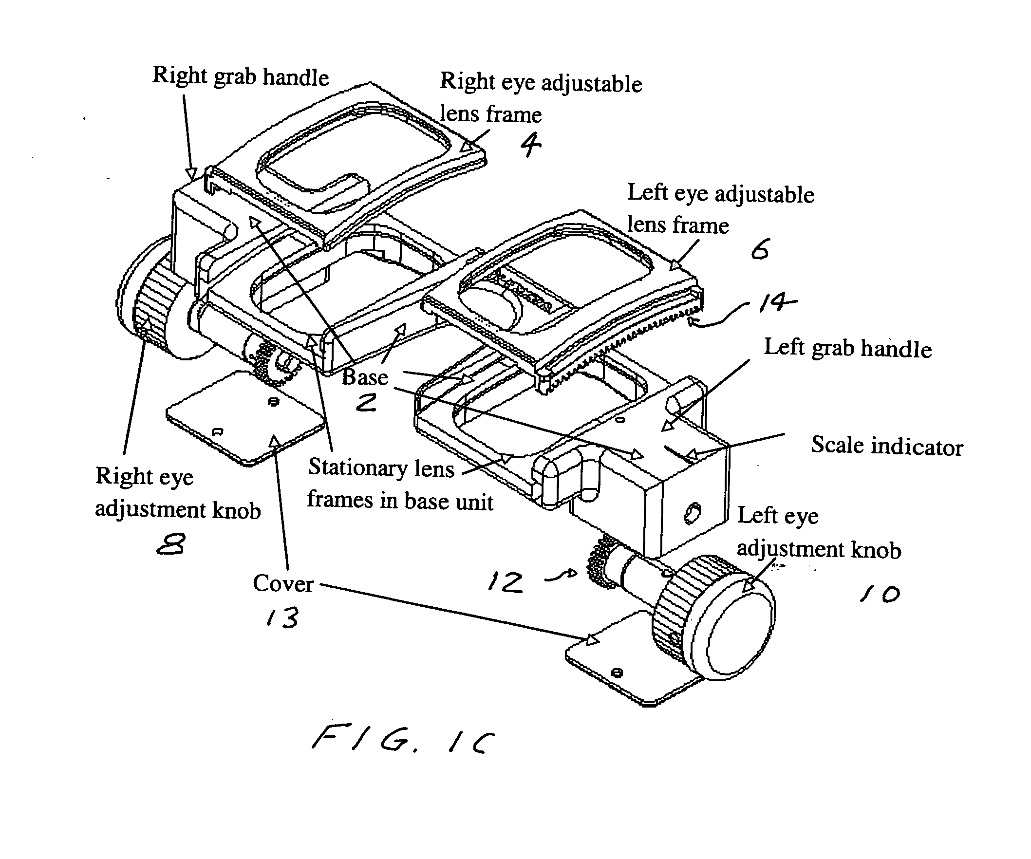
[0042]FIGS. 1A and 1B show the diopter meter in its position in front of the patient's eyes, with lens settings in the null position. A pair of lenses sits in front of each eye, the back lens is stationary and the front lens is adjustable.

[0043]The knobs on the diopter meter are turned to adjust the prescription for each eye by moving one of the lenses in each pair, independently for each eye. The diagram below shows an example adjustment. In this case the left eye has its adjustable lens adjusted down, and the right eye has its adjustable lens adjusted up. The embodiment shown in FIGS. 1A and 1B has the front lens moving up and down.

Lens Overview

[0044]The eyeglass lens manufacturing method we use is based on molded lenses according to Spivey which is a variant of the so called “Alvarez” lens shape, invented by Luis Alvarez in 1967. The Alvarez technique uses a pair of complementary third order polynomial surfaces, which are translated in a direction perpendicular to the vision dire...


PUM


Abstract

An inexpensive, easy-to-use self-refracting device which adjusts to continuously variable prescription corrections for a patient. In preferred embodiments specially designed gear arrangements, controlled by control knobs, moves one lens relative to the other or both lenses relative to each other in directions perpendicular to the viewing direction. The patient turns the device's knobs until vision is clearest. Once the patient adjusted the device for best vision, the patient's prescription can be read off various scales on the device. The diopter meter, therefore, can be used to easily and quickly screen for refractive error problems by allowing patients to self-adjust power and, if refractive error is present, see for themselves how much better they could see with corrective glasses.

Description

CROSS REFERENCE TO RELATED APPLICATIONS[0001]The present invention claims the benefit of Provisional Patent Application Ser. No. 61 / 631,000 filed Dec. 22, 2012.FIELD OF THE INVENTION[0002]The present invention relates to devices to determine the optical power needed to correct persons' vision.BACKGROUND OF THE INVENTION[0003]A diopter, is a unit of measurement of the optical power of a lens, which is equal to the reciprocal of the focal length measured in meters. It is thus a unit of reciprocal length. For example, a 3-diopter lens brings parallel rays of light to focus at one-third meter. The major benefit of quantifying a lens in terms of its optical power rather than its focal length is because the lens-makers equation has the object distance, image distance, and lens focal length all as reciprocals. A further benefit is that when relatively thin lenses are placed close together their powers approximately add. Thus a thin 2-diopter lens placed close to a thin 0.5-diopter lens yie...

Claims


Application Information

Patent Timeline
Patent Type & Authority Applications(United States)
IPC IPC(8): A61B3/04
CPCA61B3/04
Inventor SPIVEY, BRETTDREHER, ANDREAS W.
Owner SPIVEY BRETT
Why Eureka
Try Eureka