High-frequency signal line and electronic device including the same
- Summary
- Abstract
- Description
- Claims
- Application Information
AI Technical Summary
Benefits of technology
Problems solved by technology
Method used
Image

Examples
first preferred embodiment
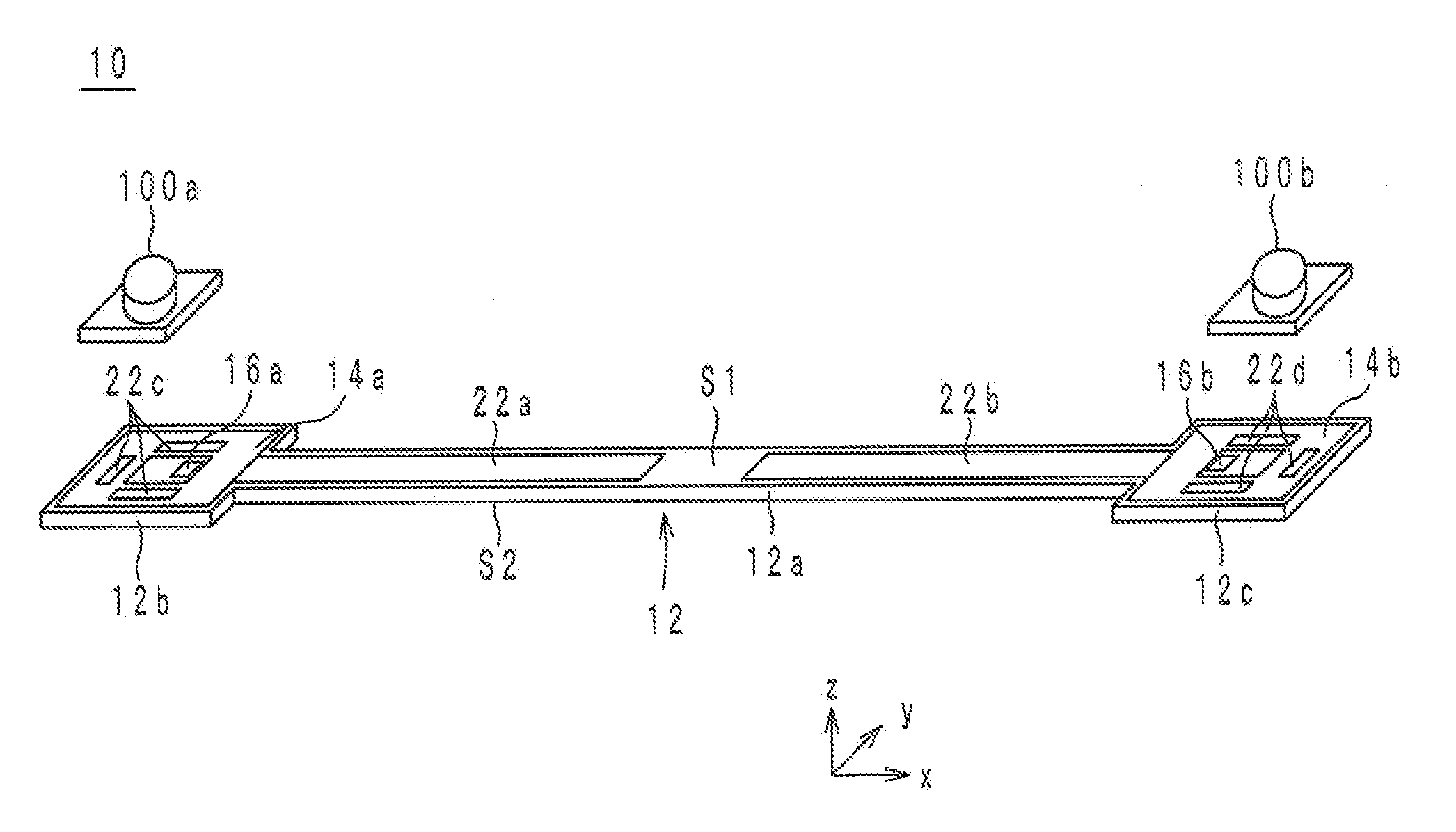
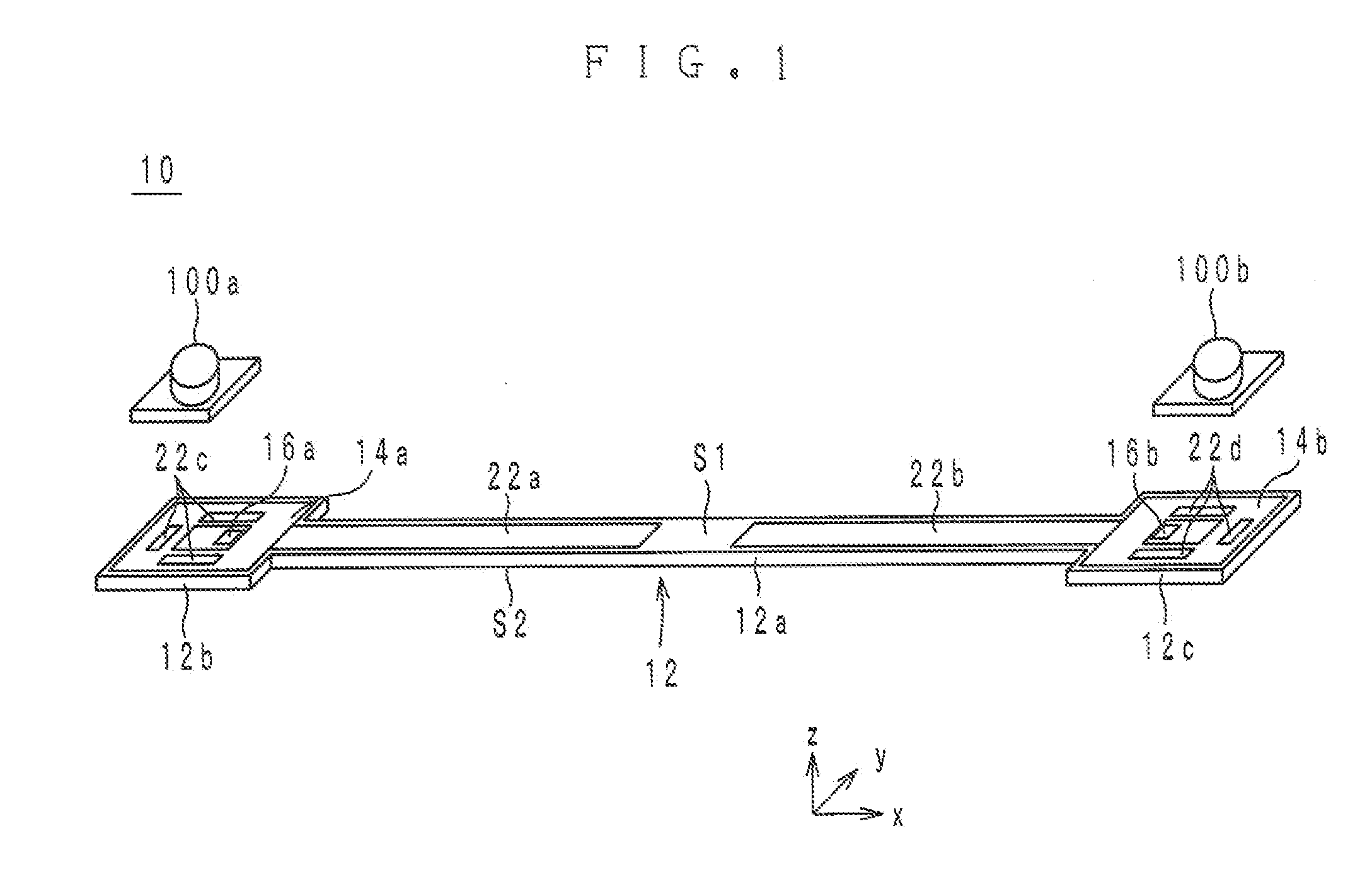
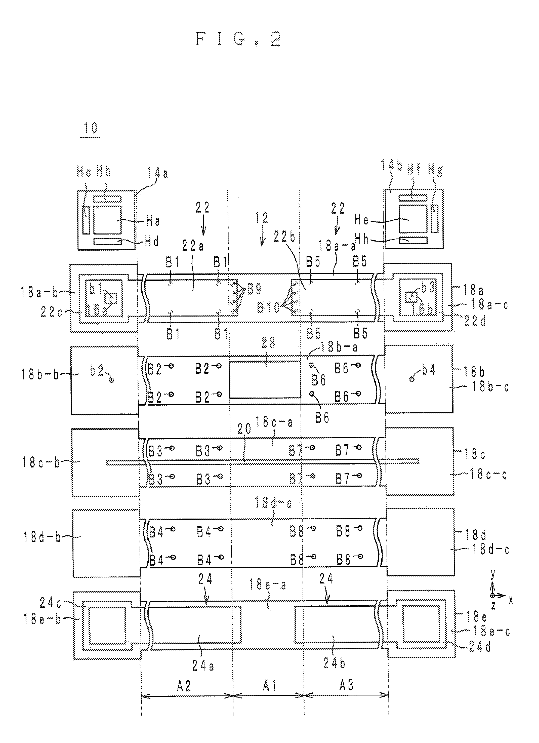
[0031]A configuration of a high-frequency signal line according to a first preferred embodiment of the present invention is described below with reference to the drawings. FIG. 1 is an external perspective view of a high-frequency signal line 10 according to the first preferred embodiment of the present invention. The high-frequency signal line 10 is preferably used as a flat cable, for example. FIG. 2 is an exploded view of a dielectric element body 12 of the high-frequency signal line 10 in FIG. 1. FIG. 3 is a cross-sectional structure diagram of the high-frequency signal line 10 in FIG. 1. FIGS. 4A and 4B are an external perspective view and a cross-sectional structure diagram, respectively, of a connector 100b of the high-frequency signal line 10. In FIGS. 1 to 4B, a stacking direction of the high-frequency signal line 10 is defined as the z-axis direction. Also, the longitudinal direction of the high-frequency signal line 10 is defined as the x-axis direction. A direction ortho...
second preferred embodiment
[0109]A configuration of a high-frequency signal line according to a second preferred embodiment of the present invention is described below with reference to the drawings. FIG. 12 is an external perspective view of a high-frequency signal line 10f according to the second preferred embodiment of the present invention. FIG. 13 is an exploded view of a dielectric element body 12 of the high-frequency signal line 10f in FIG. 12. FIG. 14 is a cross-sectional structure diagram of the high-frequency signal line 10f in FIG. 12. In FIGS. 12 to 14, a stacking direction of the high-frequency signal line 10f is defined as the z-axis direction. Also, the longitudinal direction of the high-frequency signal line 10f is defined as the x-axis direction. A direction orthogonal to the x-axis direction and the z-axis direction is defined as the y-axis direction.
[0110]As shown in FIGS. 12 to 14, the high-frequency signal line 10f includes the dielectric element body 12, protection layers 14a to 14c and...
third preferred embodiment
[0159]A configuration of a high-frequency signal line according to a third preferred embodiment of the present invention is described below with reference to the drawings. FIG. 17 is a cross-sectional structure diagram of a high-frequency signal line 10h according to the third preferred embodiment of the present invention. FIG. 18 is an exploded view of a portion of the high-frequency signal line 10h in FIG. 17, the portion being bent in a valley configuration. FIG. 19 is an exploded view of a portion of the high-frequency signal line 10h in FIG. 17, the portion being bent in a mountain configuration. In FIGS. 17 to 19, a stacking direction of the high-frequency signal line 10h is defined as the z-axis direction. Also, the longitudinal direction of the high-frequency signal line 10h is defined as the x-axis direction. A direction orthogonal to the x-axis direction and the z-axis direction is defined as the y-axis direction.
[0160]As shown in FIGS. 17 to 19, the high-frequency signal ...
PUM
 Abstract
Description
Claims
Application Information
 - R&D
- Intellectual Property
- Life Sciences
- Materials
- Tech Scout
- Unparalleled Data Quality
- Higher Quality Content
- 60% Fewer Hallucinations
Browse by: Latest US Patents, China's latest patents, Technical Efficacy Thesaurus, Application Domain, Technology Topic, Popular Technical Reports.
© 2025 PatSnap. All rights reserved.Legal|Privacy policy|Modern Slavery Act Transparency Statement|Sitemap|About US| Contact US: help@patsnap.com