
Fully substrate-isolated finfet transistor

a technology of finfet transistor and substrate, which is applied in the direction of transistors, semiconductor devices, electrical equipment, etc., can solve the problems of inconvenient installation, inability to meet the requirements of integrated circuit construction, and inability to fully isolate the substrate, so as to prevent the leakage of current from entering the device, prevent the leakage of channel-to-substrat leakage, and facilitate the removal

Active Publication Date: 2014-06-26
BELL SEMICON LLC
View PDF3 Cites 116 Cited by
  • Summary
  • Abstract
  • Description
  • Claims
  • Application Information

AI Technical Summary

Benefits of technology

The described patent text describes a method to prevent leakage in a FinFET device by using an insulating layer to isolate the channel or source / drain regions from the substrate. This results in a more reliable device where current leakage is minimized, leading to better performance and reliability. The technique also allows for the separation of the semiconducting fins from the substrate, creating a more complex and versatile device architecture. Overall, this approach improves the reliability and performance of FinFET devices.

Problems solved by technology

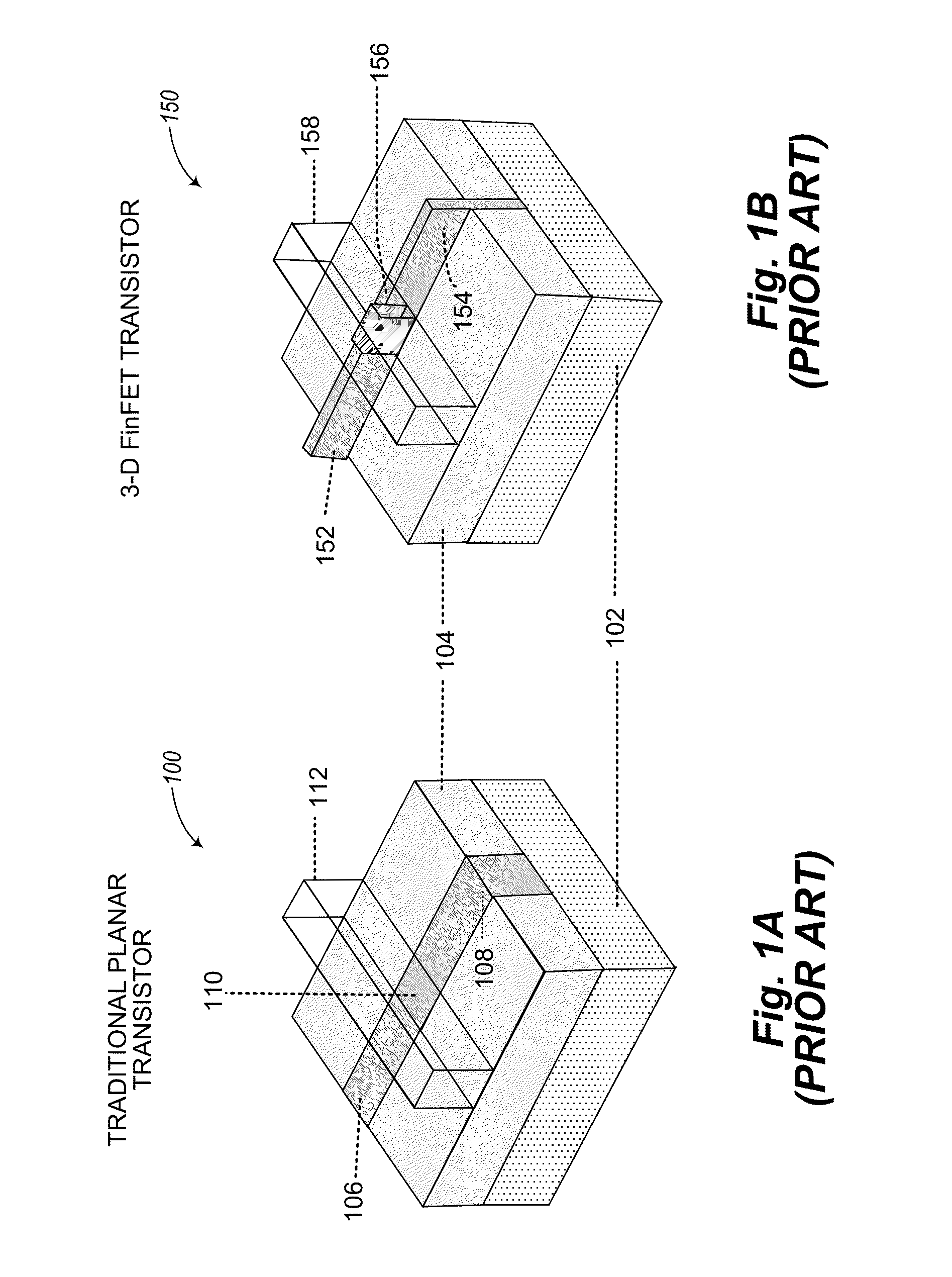
Unfortunately, a transistor is not ideal as constructed in an integrated circuit and tends to leak current even when it is off.
Current that leaks through, or out of, the device tends to drain the battery that supplies power to the device.
However, as dimensions of silicon-based transistors continue to shrink, maintaining control of various electrical characteristics, including off-state leakage, becomes increasingly more challenging, while performance benefits derived from shrinking the device dimensions have become less significant.
Despite improvements provided by three-dimensional structures and strained silicon materials, transistors continue to suffer certain types of performance degradation as device dimensions shrink into the range of 1-50 nanometers.
These include, in particular, leakage of charge between the semiconducting channel and the substrate.

Method used


Image

  • Fully substrate-isolated finfet transistor
  • Fully substrate-isolated finfet transistor
  • Fully substrate-isolated finfet transistor

Examples


Embodiment Construction

[0037]In the following description, certain specific details are set forth in order to provide a thorough understanding of various aspects of the disclosed subject matter. However, the disclosed subject matter may be practiced without these specific details. In some instances, well-known structures and methods of semiconductor processing comprising embodiments of the subject matter disclosed herein have not been described in detail to avoid obscuring the descriptions of other aspects of the present disclosure.

[0038]Unless the context requires otherwise, throughout the specification and claims that follow, the word “comprise” and variations thereof, such as “comprises” and “comprising” are to be construed in an open, inclusive sense, that is, as “including, but not limited to.”

[0039]Reference throughout the specification to “one embodiment” or “an embodiment” means that a particular feature, structure, or characteristic described in connection with the embodiment is included in at le...


PUM


Abstract

Channel-to-substrate leakage in a FinFET device can be prevented by inserting an insulating layer between the semiconducting channel (fin) and the substrate. Similarly, source / drain-to-substrate leakage in a FinFET device can be prevented by isolating the source / drain regions from the substrate by inserting an insulating layer between the source / drain regions and the substrate. The insulating layer isolates the conduction path from the substrate both physically and electrically, thus preventing current leakage. If an array of semiconducting fins is made up of a multi-layer stack, the bottom material can be removed thus yielding a fin array that is suspended above the silicon surface. A resulting gap underneath the remaining top fin material can then be filled in with oxide to better support the fins and to isolate the array of fins from the substrate. The resulting FinFET device is fully substrate-isolated in both the gate region and the source / drain regions.

Description

BACKGROUND[0001]1. Technical Field[0002]The present disclosure relates to the fabrication of integrated circuit transistors, and, in particular, low-leakage three-dimensional FinFET (field effect transistor) devices.[0003]2. Description of the Related Art[0004]In a digital circuit, a transistor is a switch which ideally: a) passes zero current when it is off; b) supplies large current flow when it is on; and c) switches instantly between the on and off states. Unfortunately, a transistor is not ideal as constructed in an integrated circuit and tends to leak current even when it is off. Current that leaks through, or out of, the device tends to drain the battery that supplies power to the device. For many years, integrated circuit transistor performance was improved by shrinking critical dimensions to increase switching speed. However, as dimensions of silicon-based transistors continue to shrink, maintaining control of various electrical characteristics, including off-state leakage,...

Claims


Application Information

Patent Timeline
Patent Type & Authority Applications(United States)
IPC IPC(8): H01L27/088H01L21/762
CPCH01L21/762H01L27/088H01L21/823431H01L27/0886H01L21/76224H01L29/0653H01L29/16H01L29/49H01L21/02532H01L21/02661H01L21/3065H01L21/308H01L21/31053H01L21/823418H01L21/823481H01L29/0847H01L29/165H01L29/66545H01L29/7848
Inventor LOUBET, NICOLASKHARE, PRASANNA
Owner BELL SEMICON LLC
Learn More