Hammer with linearly adjustable ratcheting claw

Inactive Publication Date: 2014-06-26
SMITH SCOTT L
View PDF0 Cites 4 Cited by
  • Summary
  • Abstract
  • Description
  • Claims
  • Application Information

AI Technical Summary

Benefits of technology

The invention is a hammer with a claw that can be adjusted for different sizes of nails. The hammer has a mechanism that causes the claw to move back and forth. A lever is attached to the claw and can be pushed by the nail to retract the claw. The hammer also has a magnet to secure the claw in place. The technical effects of this invention are that it makes it easier to extract nails from different sized holes and makes sure the claw remains secure while using the hammer.

Problems solved by technology

While claws are useful for fully extracting short nails in one fluid motion, long nails pose challenges.
A claw may not have sufficient length and range of motion to fully extract the nail.
Although a hammer could be provided with an extremely long curved claw sufficient to extract even the longest nail, such a hammer would be extremely cumbersome to wield.

Method used


Image

  • Hammer with linearly adjustable ratcheting claw
  • Hammer with linearly adjustable ratcheting claw
  • Hammer with linearly adjustable ratcheting claw

Examples


Embodiment Construction

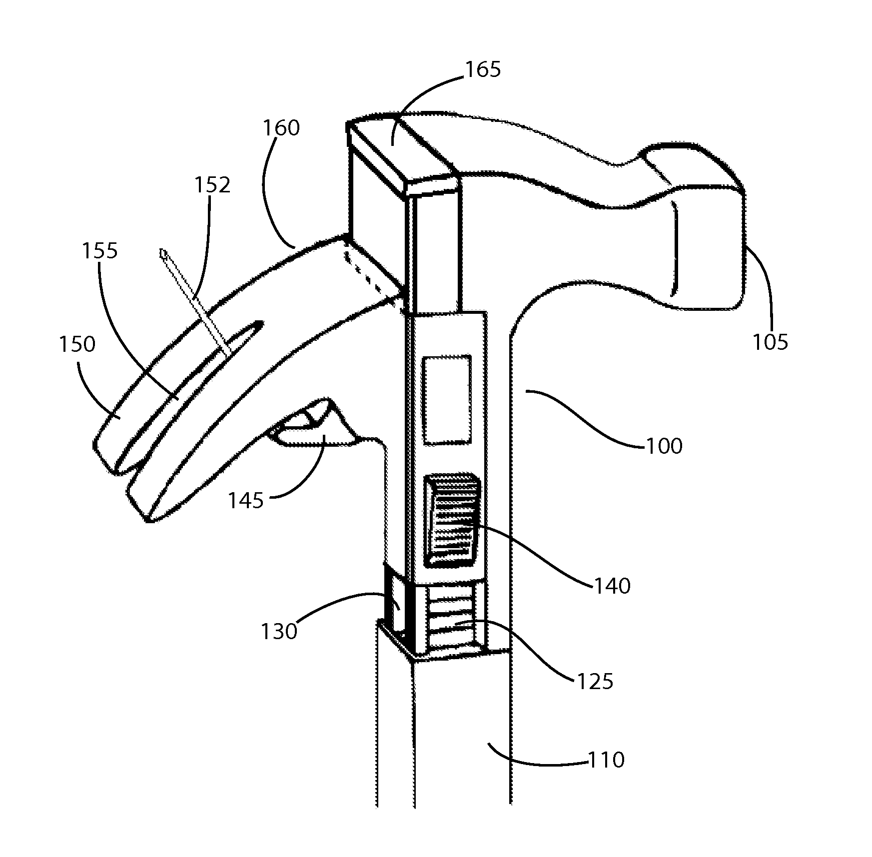
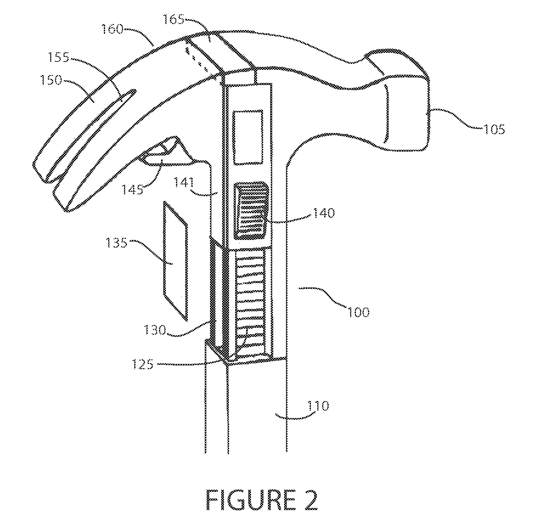
[0021]Referring now to FIG. 2, a perspective view of an exemplary embodiment of a hammer 100 with a linearly adjustable ratcheting claw assembly 160 according to principles of the invention is shown. The claw assembly 160 includes a claw 150 with a v-shaped groove 155 for engaging a nail. The claw assembly 160 is movable linearly relative to the striking head 105 of the hammer. A channel 141 is configured to receive and glide along an engaging portion of the handle. A ratcheting mechanism, which includes a manual switch 140, causes a pawl to engage and disengage a rack 125 of spaced apart teeth. The pawl and rack regulate linear movement of the claw assembly 160.

[0022]A spring compartment 130 in the handle 110 contains a compression spring 131 that urges the claw assembly towards its topmost position, as shown in FIG. 2. The spring may be a coil, leaf or other type of biasing means that resists compression. A removable cover 135 closes the opening of the spring compartment 130. The ...


PUM


Abstract

A hammer has a claw assembly that is moveable relative to the head of the hammer so as to improve leverage and range of prying for nail removal. The ratcheting mechanism may be automatic or manual.

Description

RELATED APPLICATION[0001]This application is a non-provisional and claims the benefit of priority of U.S. Provisional Application No. 61 / 739,940 filed Dec. 20, 2012, the entire contents of which are incorporated herein and made a part hereof.FIELD OF THE INVENTION[0002]This invention relates to claw hammers, and, more particularly to a claw hammer with a claw that is moveable relative to the head of the hammer so as to improve leverage and range of prying for nail removal.BACKGROUND[0003]As is well known, a conventional claw hammer is a tool primarily used for pounding nails into or extracting nails from some other object. Generally, a claw hammer is associated with woodworking but is not limited to use with wood products.[0004]A conventional claw hammer 10 is illustrated in FIG. 1. From a profile, it roughly resembles the letter “T”. The handle 15 is the long vertical part. The head assembly 20 includes a striking head 25 and a curved two-prong claw 30 opposite the striking head. T...

Claims


Application Information

Patent Timeline
IPC IPC(8): B25D1/04
CPCB25D1/04B25D2250/005B25D1/06B25D1/045
Inventor SMITH, SCOTT L.
Owner SMITH SCOTT L
Why Eureka
Try Eureka