
Harvesting platform having angled crop converging auger

a technology of converging auger and harvesting platform, which is applied in the direction of mowers, agriculture tools and machines, and mowers, etc., can solve the problems of increasing power consumption and crop re-cutting

Active Publication Date: 2014-06-26
DEERE & CO
View PDF2 Cites 18 Cited by
  • Summary
  • Abstract
  • Description
  • Claims
  • Application Information

AI Technical Summary

Benefits of technology

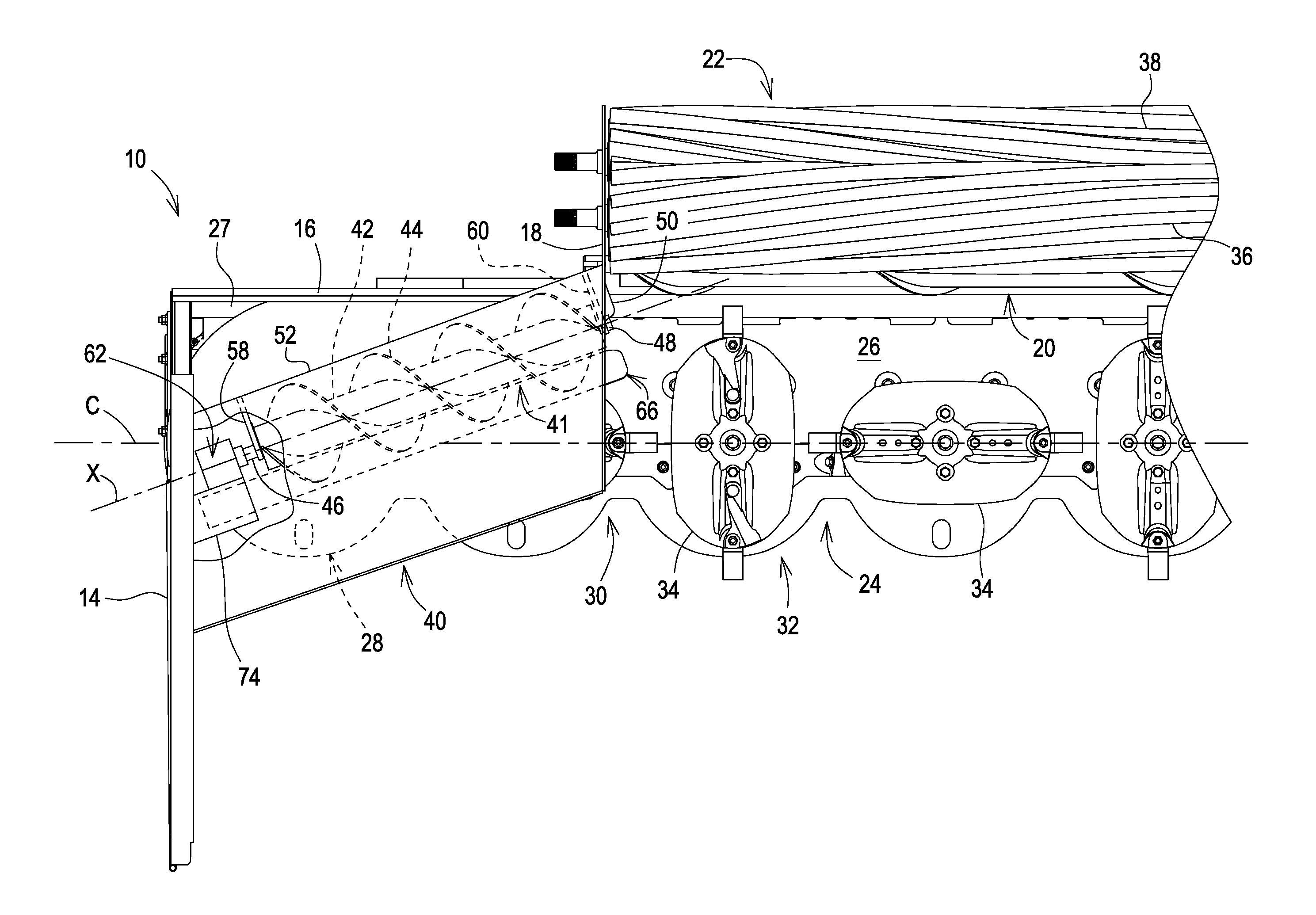
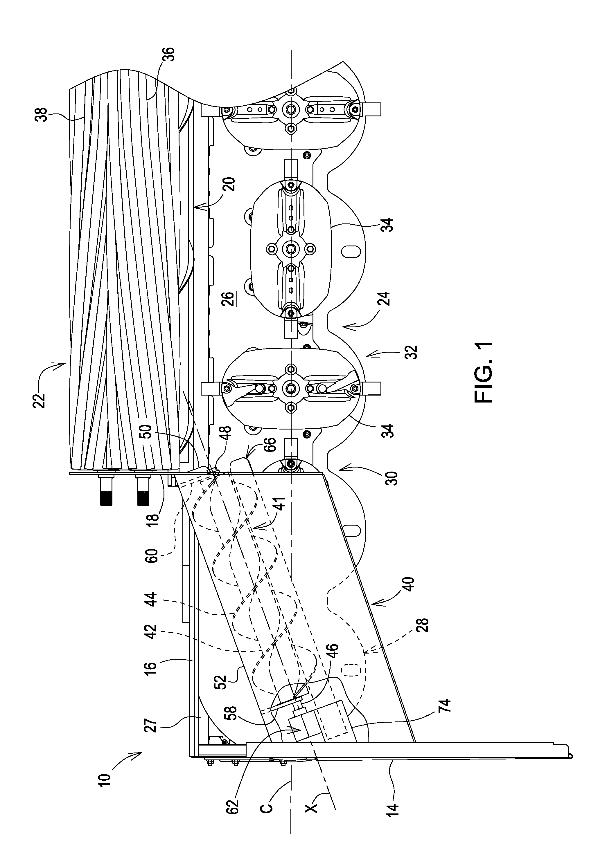
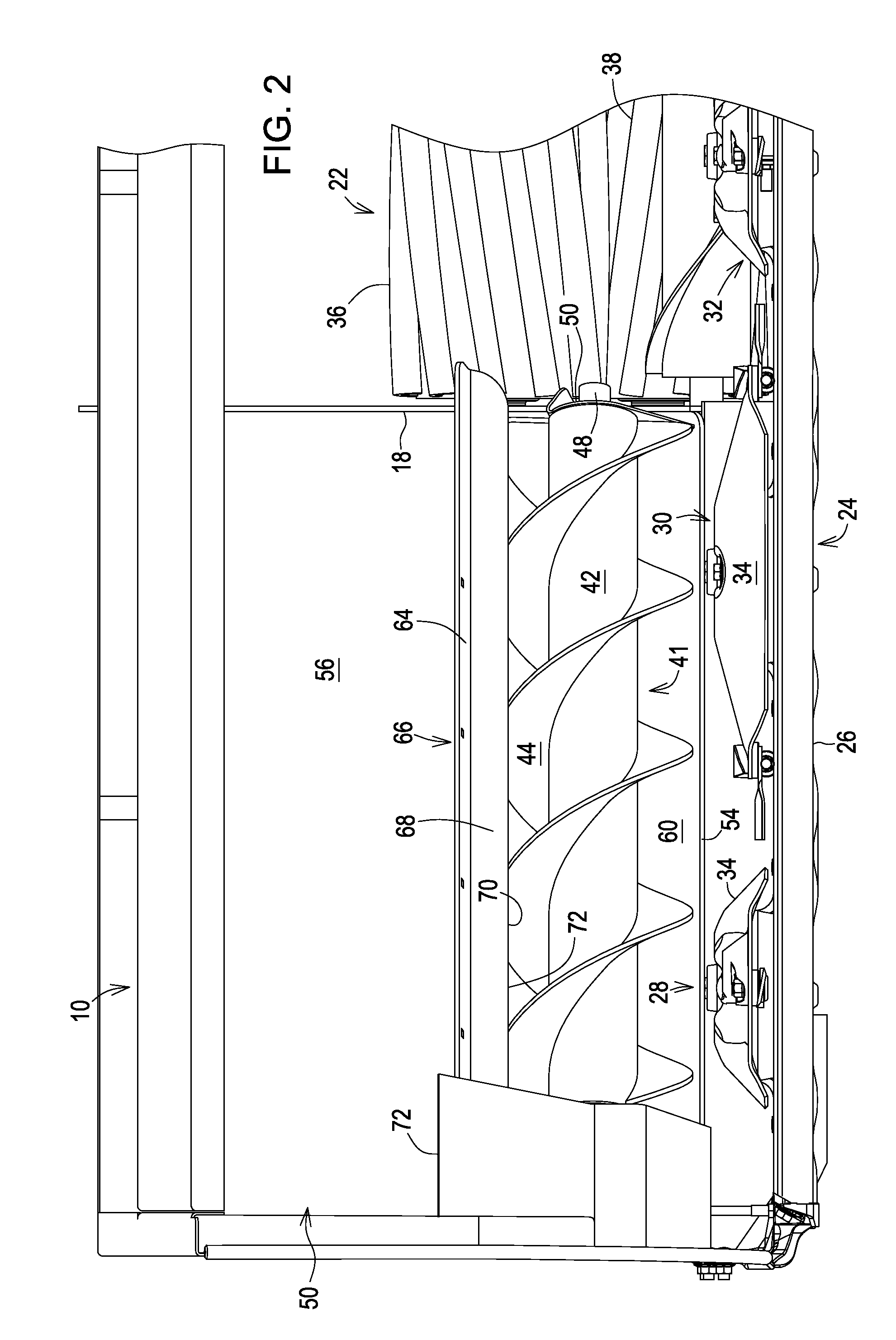
The present invention provides a harvesting header with a crop conditioner that has a width less than that of the header. The crop is delivered to the conditioner by an improved crop converging apparatus. The invention includes right and left augers that have axes that converge towards the rear of the header. Technical effects include improved crop conditioning, faster and more efficient crop delivery, and reduced crop damage.

Problems solved by technology

The following is a list of different converging apparatus used on current production crop harvesting machines of the stated type together with a disadvantage associated with the stated converging apparatus:1) An undershot converging auger located behind and extending parallel to the cutter bar, having the disadvantage of not lifting the crop off the rotating cutter discs, resulting in the crop being re-cut and in increased power consumption;2) U.S. Pat. No. 8,161,719 discloses an overshot converging auger having an axis that extends parallel to the axes of rotation of the conditioner rolls, having the disadvantage of the crop delivery paths of the opposite end sections of the auger are not direct;3) A pair of outboard, vertical axis converging drums are provided at the opposite sides of the header and used together with an inboard stub auger having an axis that is parallel to those of the conditioner rolls, having the disadvantage of crop sometimes becoming wedged between the drums; and4) Three outboard vertical axis converging drums are arranged along a line extending inward and to the rear from the adjacent side, having the disadvantage of crop sometimes becoming wedged between the drums.

Method used


Image

  • Harvesting platform having angled crop converging auger
  • Harvesting platform having angled crop converging auger
  • Harvesting platform having angled crop converging auger

Examples


Embodiment Construction

[0016]Preliminarily, it is to be noted that while some structure may be stated as occurring in pairs or as being right- and left-hand members, only one of the pair, or one of the right- and left-hand members may be shown, with it to be understood that the other member is identical to, or a mirror image of, the one shown.

[0017]Referring now to FIGS. 1 and 2, there is shown a portion of an exemplary mowing implement which would benefit from using the present invention, the mowing implement here being embodied as a wide cut mower-conditioner harvesting platform 10 which may be carried at the forward end of a self-propelled mower-conditioner, for example. The platform 10 includes a trough-shaped top frame member 12 (FIG. 3) extending between, and joined to, upper rear regions of right- and left-hand outer side walls, of which only the right-hand outer side wall 14 is shown. Left- and right-hand upright transverse bulkheads, of which only the right-hand bulkhead 16 (FIG. 1) is shown, ext...


PUM


Abstract

A wide cut harvesting platform includes a rotary cutter bar having right- and left-hand outer and inner cutting units having respective inner and outer cutting discs at its opposite ends rotating in appropriate opposite directions for conveying cut crop from outer ends of the cutter bar to a central crop discharge path leading to a crop conditioning arrangement extending across the path. A first embodiment includes horizontal, right- and left-hand converging augers mounted so as to diverge forwardly above inner and outer cutting discs at the opposite ends of the cutter bar from locations at opposite sides of the discharge path and forward of the conditioner arrangement. A second embodiment includes first and second forwardly diverging augers like the first embodiment but being shorter and respectively terminating outwardly adjacent right- and left-hand converging drums respectively mounted to, and for rotating together with the right- and left-hand outer cutting discs.

Description

FIELD OF THE INVENTION[0001]The present invention relates to wide crop harvesting platforms or headers having widths greater than crop conditioners to which rotary cutter bars of the platforms convey cut crops, and more specifically relates to apparatus for aiding in the convergence of the cut crop into the conditioners.BACKGROUND OF THE INVENTION[0002]Current production crop harvesting machines of the type having platforms for cutting a wide swath of standing crop are equipped with various crop converging apparatus designed for aiding in the conveyance of outboard severed crop toward conditioner apparatus located across a central crop discharge region of the platforms for receiving and conditioning the cut crop. One production platform, for example, includes a plurality of conveyor drums located at each side of the central crop discharge region and mounted for rotation about respective upright axes, with an outermost drum at each side of the crop discharge region being mounted for ...

Claims


Application Information

Patent Timeline
IPC IPC(8): A01D43/077
CPCA01D43/10A01D34/664A01D34/668A01D61/004A01D43/077
Inventor STEPHENSON, ROGER D.ROSENBALM, ALLAN W.SLOAN, CHARLES S.
Owner DEERE & CO
Learn More