
Automatically adjusting patella cutting guide

a cutting guide and automatic adjustment technology, applied in the field of patellar saw guide, can solve the problems of deformation of the articulating surface of the knee, and achieve the effect of facilitating the preparation of the natural patella

Active Publication Date: 2014-06-05
HOWMEDICA OSTEONICS CORP
View PDF4 Cites 4 Cited by
  • Summary
  • Abstract
  • Description
  • Claims
  • Application Information

AI Technical Summary

Benefits of technology

The system provides a secure and adjustable clamping mechanism that allows for precise resection of patellar bone, ensuring sufficient bone stock remains for prosthetic fixation pegs and maintaining the integrity of the patellar bone.

Problems solved by technology

Because of aging or disease, the articulating surfaces of the knee may degrade.

Method used


Image

  • Automatically adjusting patella cutting guide
  • Automatically adjusting patella cutting guide
  • Automatically adjusting patella cutting guide

Examples


Embodiment Construction

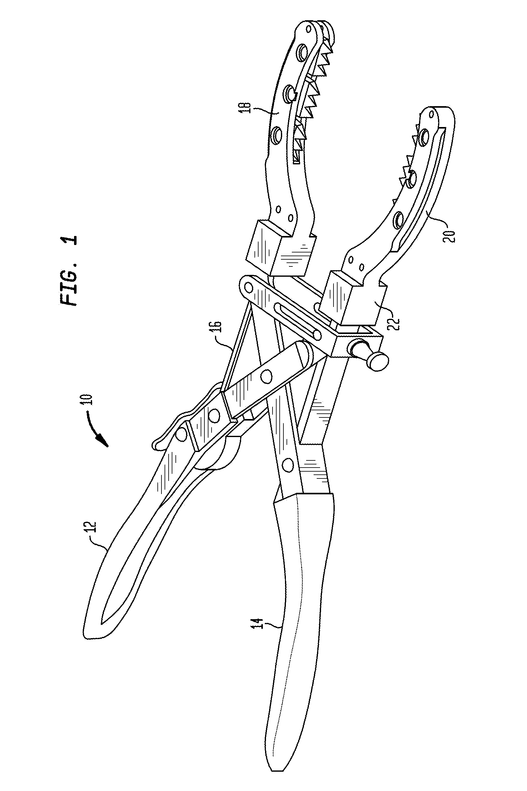
[0036]Referring to FIG. 1, there is shown a patella clamping device generally denoted as 10 which includes a handle portion including two gripping members 12 and 14. Gripping members 12 and 14 engage a pivot section 16 which is capable of moving a first jaw arm 18 towards a second jaw arm 20. Pivot section 16 may include one or more pivot pins and / or a linkage system for transferring the action or gripping member 12, 14 to jaw arms 18, 20. The linkage system may move jaw arms 18, 20 in parallel. The jaw arms 18 and 20 may be removably coupled to clamping section 16. The handle portion and pivot section of the patella clamping device 10 are known in the prior art and are shown, for example, in U.S. Patent Application Publication No. 2007 / 0118141, the disclosure of which is incorporated herein by reference.

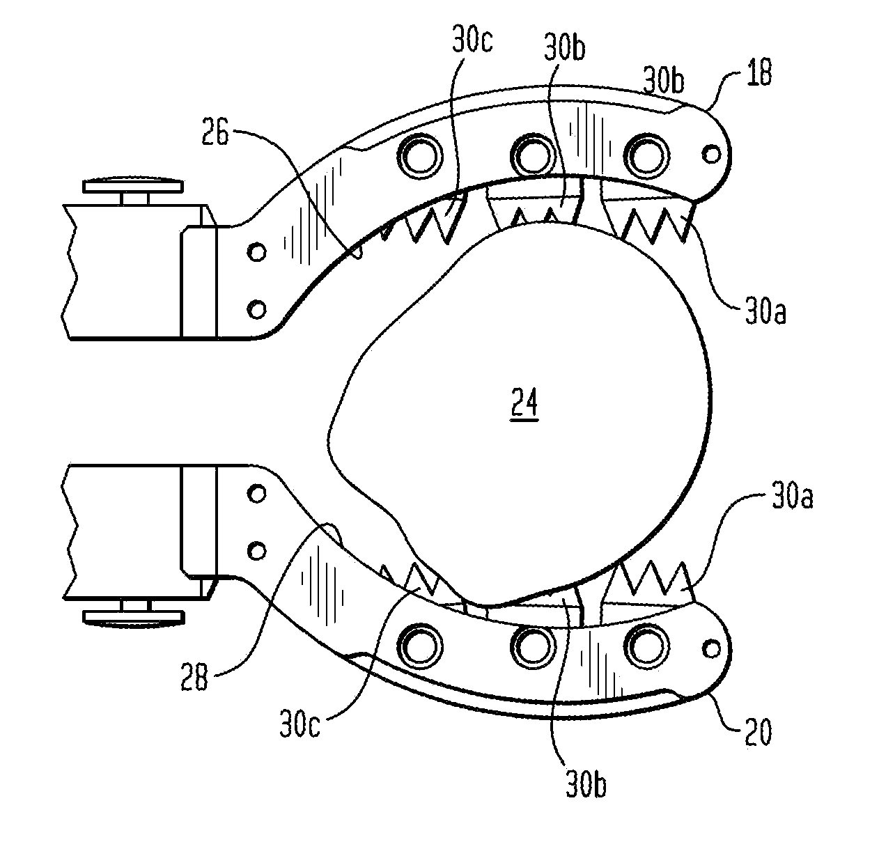
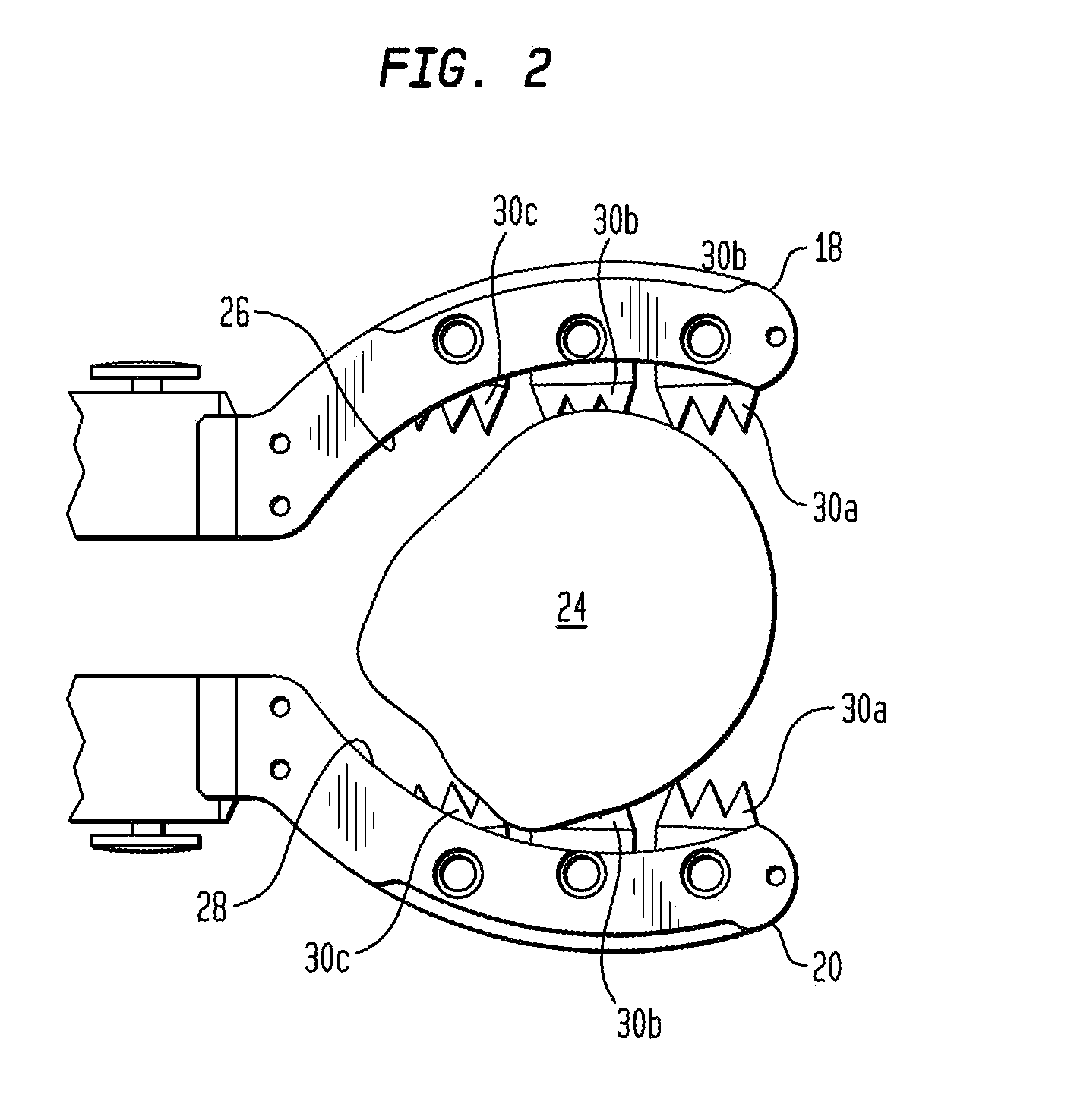
[0037]Referring to FIG. 2, there is shown a top view of the two clamping jaw arms 18 and 20 surrounded and clamping a patella 24. Arms 18 and 20 are arcuate and have concave surface...


PUM


Abstract

A patella clamping device has a handle having a first arm and a second arm, the arms each having a first gripping end and a second clamping end. The clamping ends are movable towards the opposite arm by action on the gripping end of each arm. The clamping ends of the first and second arms comprise opposed clamping surfaces. The clamping end of each arm has a body portion having spaced first and second surface defining the opposed surface of each arm. A plurality of pins extend from the first to the second surface. A rotatable toothed jaw member is pivotally mounted on each of the pins. The jaw member has at least one tooth extending outwardly of the opposed surface of each arm for engaging the patella. Each body has a third surface spaced from the second surface to create a slot for receiving a saw blade.

Description

CROSS-REFERENCE TO RELATED APPLICATIONS[0001]This application is a divisional of U.S. application Ser. No. 12 / 903,470 filed Oct. 13, 2010, the disclosures of which are incorporated herein by reference.BACKGROUND OF THE INVENTION[0002]The invention relates to a patellar saw guide which has a plurality of rotatable teeth adapted to engage an edge of a patella prior to its preparation for receiving a prosthetic implant.[0003]A patellar clamp and saw guide are used during a total knee arthroplasty procedure to prepare the posterior surface of a patellar bone to accept a prosthetic implant.[0004]Typically, a surgeon will select a patellar prosthesis for implantation either by utilizing a resurfacing technique wherein the prosthetic patella will be resected and resurfaced and / or by an insetting procedure where the prosthetic patella is inserted into the prepared surface of the patella.[0005]The patella is a sesamoid or lens shaped bone which slides in a groove between the condyles of the ...

Claims


Application Information

Patent Timeline
Patent Type & Authority Applications(United States)
IPC IPC(8): A61B17/17
CPCA61B17/1767A61B17/158Y10T29/539
Inventor SOLIMAN, MOHAMEDMCMILLEN, TROY ALLENLEONARD, ROBERT J.
Owner HOWMEDICA OSTEONICS CORP
Learn More